Week 2:- BiW Fixture Basics Challenge
1. BIW PROJECT ACTIVITIES:
project activites is the series of activities starting with reciving data for the projects from the customer to final handover of the project.
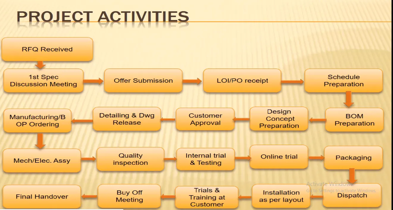
RFQ RECIVED:
RFQ is REQUEST FOR QUOTATION.Data and other informations related to the projects are recived from the customer.The data includes dimensions , tolerances and other datas requires for design the project.After reciving the RFQ from the customer the datas and informations are studied and checked that the given data is enough for design the project.
OFFER SUBMISSION:
After reciving the RFQ and studied the RFQ from the customer, the time required to complete the project and cost involved in design and manufacturing of the project is submitted to the customer is called offer submission.The customer recives different offer from different project industries and compare those offers and select which one is best for him.
Example for offer submission:
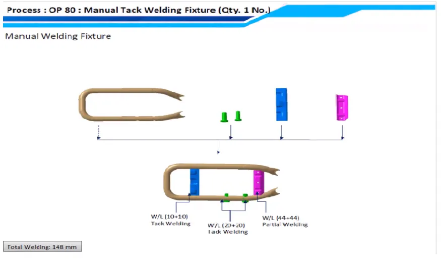
Fixture to be modified for full robotic welding.
Consideration of child parts,
Design & Detailing: 15 hrs , Simulation: 3-4 hrs.
Manufacturing: Trunion frame &12-15 blocks.
Brought-outs: motor,gearbox,bearings,sensor,shaft,electrical fittings,etc.,
Assembly,Installation & comissioning: 15-16 hrs.
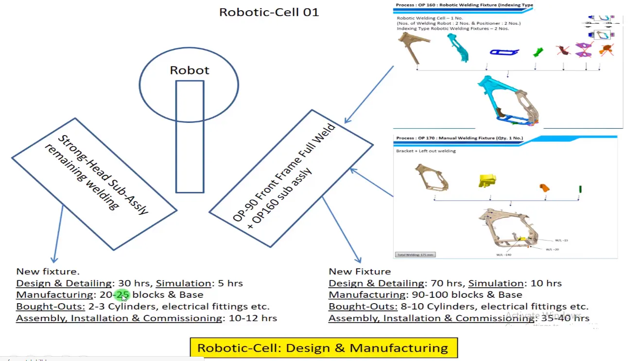
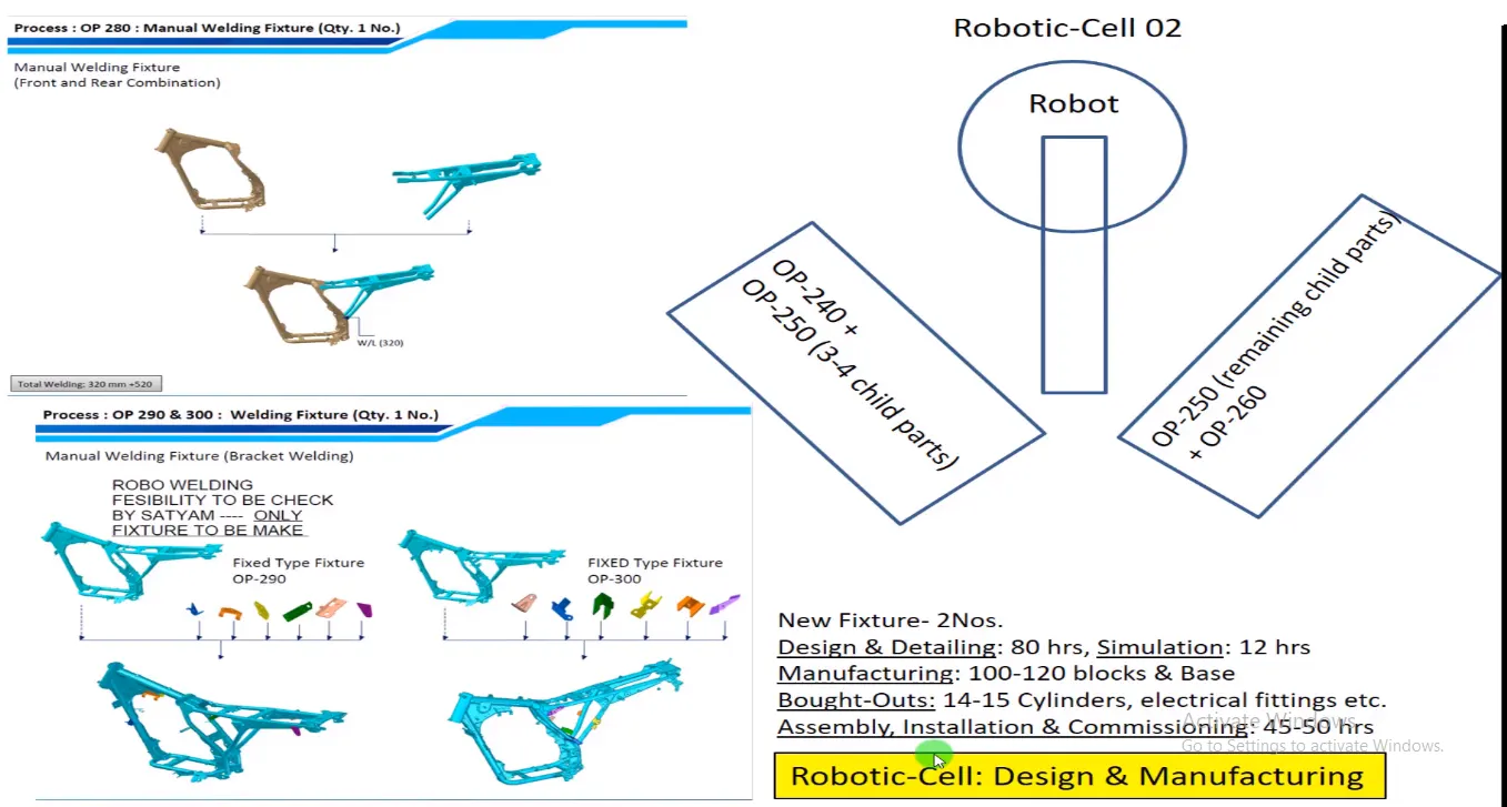
TOTAL: New fixtures (4 nos) & modified fixtures (2/3 nos).
Design & Detailing: 200 hrs.
Simulation: 40 hrs
Manufacturing: Around 300-350 hrs + 3-4 bases.
Brought-outs: 25-30 cylinders,motors,gearbox,bearings,shaft,electrical fittings etc.,
Assembly , installations & comissioning: 150 hrs.
LOP/PO RECIVED:
After offer submission , If the customer accepts the offer submission, he will give the LOI/PO (purchase order).After PO is recived from the customer plan schedule is prepared to begian the project.
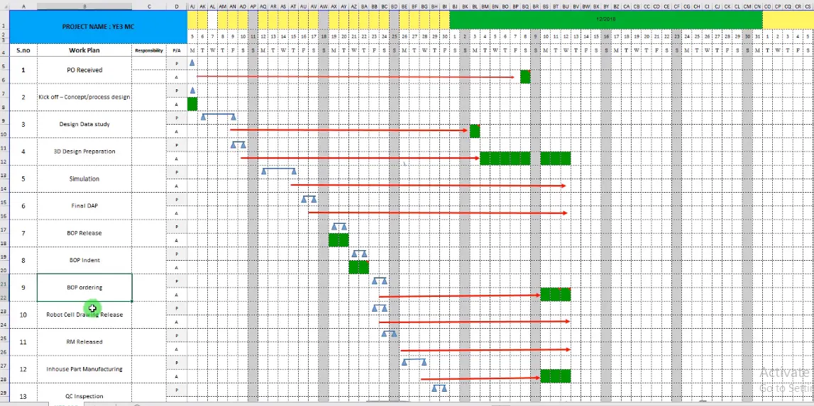
From the above schedule,it shows the process and its duedate.After po recived on monday kick off - concept begains on the same day.design data studies take place for three days . In that way schedule is prepared.
BOM PREPARATION:
Bill of materials(BOM) which is required to manufacture the projects is prepared after the process of schedule preparation is completed.
DESIGN CONCEPT PREPARATION & CUSTOMER APPROVAL:
Design concept is prepard as per the customer requirements and it is checked by the quality control . They check the dimensions, tolerances and materials is as per the requirements.If everything is alright it will be delivered to the customer for approval. He again checks the design for his requirements, if there is any deviation he resends and coorect the deviations.Orelse he wants to add something or make changes in his requirements, then the industry has to make changes as per the curtomer requirements.And if he approved the design concept then detailing & drawing of design is started.
DETAILING AND DRAWING RELEASE:
After design is approved by the customer,then detailed design and drawing of the project is released to manufacture the parts. Details such as full dimension requred to manufacture the par and its tolerences such as run out,face out,ovality etc., are released to the operator.
MANUFACTURING/BOP ORDERING:
With the help of dtailed drawing the process of manufacturing the parts are started.And the brought out products (BOP) are ordered for the assembly of the project.
MECH/ELEC.ASSEMBLY & INSPECTION:
After the parts are manufactured ,then those parts are assembled together with the brought out parts such as motor, gearbox,electrical fittings etc.,Oncethe assembly is carried out then which is inspected by the qyality control again for its dimensions and tolerences which is as per the design.If there is any deviation in the dimensions that part is dismantled and replaced with correct part.But it takes time and waste of material and labour cost.
INTERNAL TRAIL,TESTING & ONLINE TRAIL:
Inspected assembly is taken for internal trail which means the assembly is tested within the industry to check every parts are work without any problem.Then online trail is carried out, in online trail the assembly is simulated in computer.
PACKAGING AND DISPATCH:
If the assembly is tested then it is packed and dispatched to the customer.
INSTALLATION:
The assembly is installed as per the layout given by the project industry and its is gone for trail. Then the training is given to the customer so that he kows how to work on it.
BUYOFF MEETING & FINAL HANDOVER:
The meeting is held , if there is improvement needed by the customer in the project. Orelse if everything os ok then the project is finally handover to the customer and ready for mass production.
2.TYPES OF JOINING PROCESS:
There are two types of joining process:
- Mechanical joining.
- metallurical joining.
RESISTANCE WELDING:
Resistance welding is a welding technology widely used in manufacturing industries to join metal sheets and components.The weld is made by strong current through the metal combination to heat up and finally melt the metals at localised points predetermined by the design of the electrodes and the work pieces to be welded.
types of resistance welding:
- Resistance spot welding.
- Resistance projection welding.
- Resistance seam welding.
- RESISTANCE SPOT WELDING:
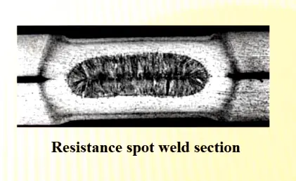
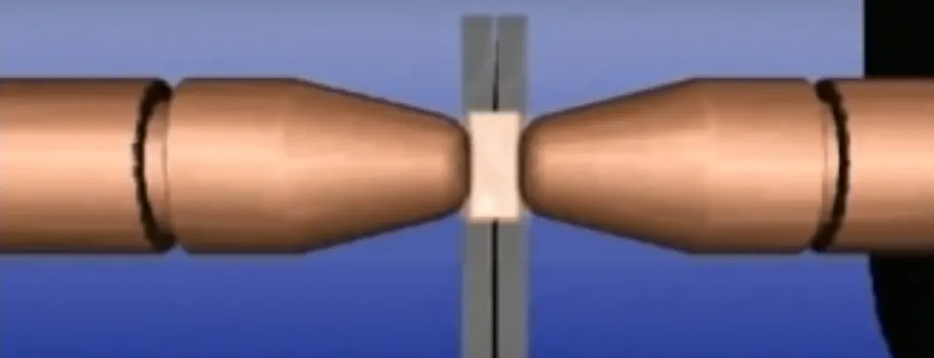
The process is used for joining the metal sheets and uses shaped copper-chromium or zirconium alloys electrodes to apply pressure and convey the electrical current through the workpieces.heat is developed in the interface of the two metal , eventually causing the material to be welded to melt,forming an molten pool,the weld nugget.
Advantages:
1.Short weld time and high weld speed.
2.Highly acceptable for automation and robotic techniques.
3.Typically BIW contains 5000 welds.
4.Strength and durability is largely depends on quality of RSW.
- RESISTANCE PROJECTION WELDING:
Projection welding is a resistance welding process for joining metal components or sheet metal embossments by direct applyingopposing forces with electrodes espically designed to fit the shape of the workpieces.
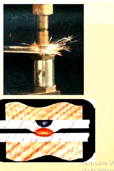
The current and heat generation are localized by the shape of the workpiece either with their natural shape or specially designed projection.Large deformation or collape will occcur in the projection part of the workpieces implying high.
Application:
1. used in mechanical fixing of autobody structures. eg., Weld nuts.
- RESISTANCE SEAM WELDING:
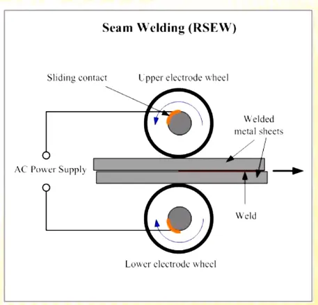
Seam welding is a resistance welding process for joining sheet metals continously,often leaktight.seam joints by directly applying opposing forces with electrodes consisting of rotary wheels.The current and heat generation are localized at the peripheral shape of the electrode wheels.
Applications:
seam welding is mostly applied in manufacturing of containers,radiators ,heat exchangers etc.,
ARC WELDING:
The process involvedeither consumable or non consumable electrode(rod or wire).an arc is produced at the interface between the tip of the electrode and the workpiece to be weld, by use of an AC or DC supply.
TYPES OF ARC WELDING:
1.Mannual metal arc welding (MMA).
2.Gas - sheilded metal arc welding (METAL INERT GAS WELDING-MIG).
3.Gas - sheilded tungsten arc welding (TUNGSTEN INERT GAS WELDING-TIG)
4.Submered arc welding.
5.Plasma arc welding.
- MANUAL METAL ARC WELDING (MMA):
Manual metal arc welding (MMA or MMAW) is also called sheilded metal arc welding (SMAW) or informally called as STICK WELDING).Stick welding is a process where the arc is struck between the metal rod and with work piece,both the rod and workpiece surface weld to melt.
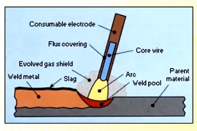
Process may be applied to the most commenly used metals and alloys such as carbon and alloy steels,stainless steel, copper-nickle and their alloys.
APPLICATIONS:
Used in short welds espicially in production,maintenance,prepare & construction.
BENEFITS:
1.Simple,expensive & portable.
2.Welding at any position is possible at appropration electrode is choosen.
LIMITATIONS:
It is not suitable for low melting metals such as Tin,lead or zinc or more oxygen reacted metals such as aluminium,titanium, zirconium metals.
- GAS - SHEILDED METAL INERT GAS WELDING (MIG):
The main equipment required for mig welding are AC or DC supply,welding torch or gun,wire electode,sheilding gas cylinder,cooling system and remote current control. Welding gun utilizes consumable electrode .The consumable electrode feed from the rod.The wire rod is opperated by wire feed drive motor and is controlled by wire feeder system.
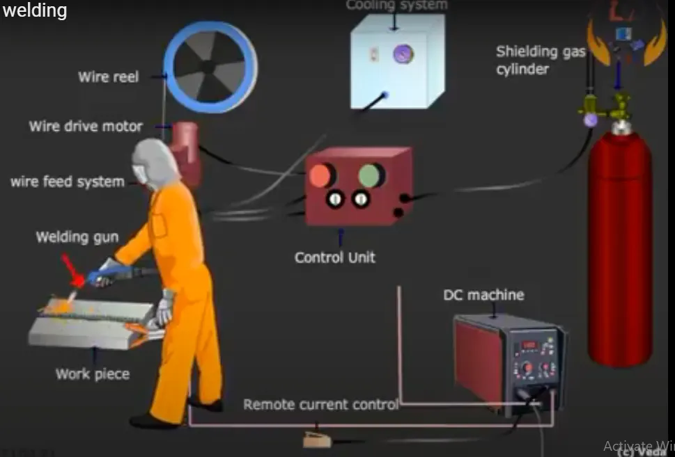
This MIG is also called as semi automated arc welding & automated arc welding is done by robot.
BENEFITS & APPLICATIONS:
1.It is used for thick and lage materials.
2.It empoyes a consumable wire that act as the both electrode and the filler material.
3.compared to tig it is much faster resulting shorter lead time & lower production cost.
- GAS - SHEILDED TUNGSTEN INERT GAS WELDING (TIG):
Tungsten inert gas welding(TIG) is also known as gas tungsten arc welding(GTAW) is an arc welding method that uses anon-consumable tungsten electrode to weld two or more workpieces.It is very much similar to MIG welding.
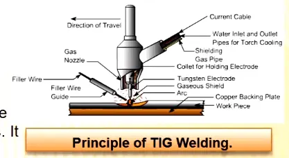
The weld area is protected from atmospheric contamination by a sheilding gas ( usually inert gas such as argon) and a filler metal is normally used ,through some welds known as autogenous welds do not require it.Filler rod is added mannualy to the front end of the weld.
Filler rod is composed of metals with low melting temprature such as aluminum ,require that operator maintain some distance from the arc while staying inside the gas sheild.The necessary components are power supply,non-consumable metal electrode ,inert gas supply,filler rod and weld head
MECHANICAL FASTENING:
The joining of material combination which cannot be easily welded such as pre painted steels or very dissimilar metals.
eg: AL application in autobody make use of mechanical fastening techniques to overcome the poor inerhent weld ability of AL.
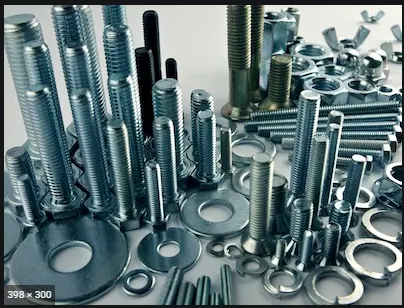
The joining of materials in applications where high fatigue life is critical compared to static strength.The joining of materials where a long tool life is of relative importance.
eg; screws & bolts.
SELF PIERCING RIVETS:
Self piercing rivets is a hogh speed mechanical fastening process for point joining sheet metal typically sheets and alluminium alloys.It is a single step technique generally using a semi turbular rivet to clinch the sheets in a mechanical joints .There is also a process varient which utilizes solid rivets.
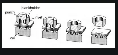
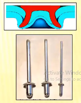
As the name suggests ,predrilled holes are not required allowing the jint to be made rapidly in one operation.
3.REISTANCE WELDING:
RESISTANCE WELDING:
Resistance welding is a welding technology widely used in manufacturing industries to join metal sheets and components.The weld is made by strong current through the metal combination to heat up and finally melt the metals at localised points predetermined by the design of the electrodes and the work pieces to be welded.
types of resistance welding:
- Resistance spot welding.
- Resistance projection welding.
- Resistance seam welding.
- RESISTANCE SPOT WELDING:
The process is used for joining the metal sheets and uses shaped copper-chromium or zirconium alloys electrodes to apply pressure and convey the electrical current through the workpieces.heat is developed in the interface of the two metal , eventually causing the material to be welded to melt,forming an molten pool,the weld nugget.
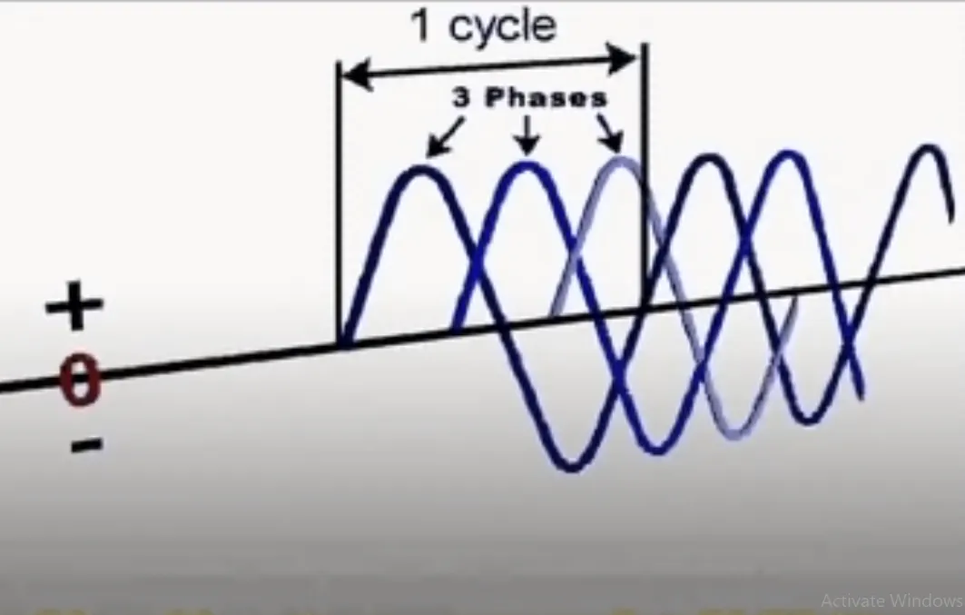
Current supply is more important in resistance spot welding .If we supply a AC current to the electrodes,its leads to fluctutation in welding and it won't be smooth.Because AC supply is in sine wave in which the power is down to zero for three times in one wavelength.
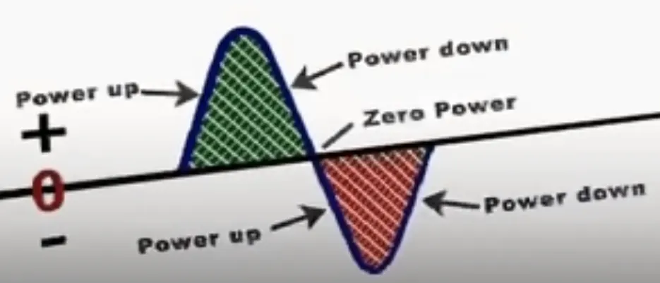
If we use a DC power supply ,the current flow is better than ac supply.In three phase DC supply the weld will be even more smoother .Because in one wavelength three power up takes place.There will be no power down to zero.AC is converted to DC supply through diode rectifier.
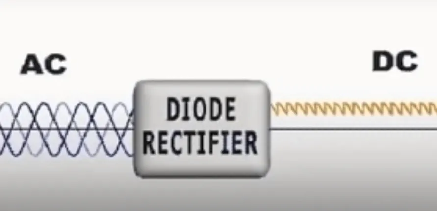
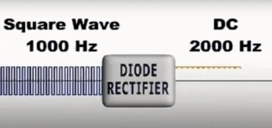
The weld is more smoother if the ac supply is passed through inverted before passing diode rectifier.The AC sine wave is converted to square wave with 1000 Hz freequency through inverter.Then the diode rectifier converts the square wave into dc suppply with frequency of 2000 Hz.

Advantages:
1.Short weld time and high weld speed.
2.Highly acceptable for automation and robotic techniques.
3.Typically BIW contains 5000 welds.
4.Strength and durability is largely depends on quality of RSW.
APPLICATIONS:
1. It mostly used in automobile industry and to weld sheet metal for mostly.
2. In orthodontist's clinic ,small spot weld equipment used to resizing the metal'molar bands'.
3. The different metalsand aloy steels, medium carbon steel and high carbon sttels,low carbon steels can be welded.
- RESISTANCE PROJECTION WELDING:
Projection welding is a resistance welding process for joining metal components or sheet metal embossments by direct applyingopposing forces with electrodes espically designed to fit the shape of the workpieces.
In resistance projection welding , small projections are formed on one or both pieces of base metal to obtain contact at a point which helps the current flow and develop heat.Under pressure heat is developed and the projections collapse and weld is formed.projection in the upper side is pressed against the lower component by the electrode force.This technique is of special value mounting attachments to surface of which the back side is inaccess to the welding operator.
The current and heat generation are localized by the shape of the workpiece either with their natural shape or specially designed projection.Large deformation or collape will occcur in the projection part of the workpieces implying high.
Advantages:
1.Resistance projection welding is not limited to sheet to sheet joints.
2.projection welding can be done in specific points which are desired to welded.
Disadvantages:
1.Projection need to have same height for approprate welding.
2.There is an extra operation which is called forming of projection.
Application:
1. used in mechanical fixing of autobody structures. eg., Weld nuts.
2. Projection welding is used in refrigration works( mass production of condensers, gratings, racks etc.,)
- RESISTANCE SEAM WELDING:
Seam welding is a resistance welding process for joining sheet metals continously,often leaktight.seam joints by directly applying opposing forces with electrodes consisting of rotary wheels.The current and heat generation are localized at the peripheral shape of the electrode wheels.
Applications:
1.seam welding is mostly applied in manufacturing of containers,radiators ,heat exchangers etc.,
2.resistance seam welding canbe used to make gas or fluid tight joints in a variety of sheet metal fabrications. eg;steel fuel tanks for motor vehicles
3.Acess to both sides of joints is necessary and a lap joint configation is generally required.
4.Components compraising two half shells maybe welded. eg; petrol tanks, domestic radiators.
5.Sheets can be rolled into turbular form and the longitudinal seam welded,as in tin cans or steel drums.
4.FUSION WELDING :
Fusion welding is a process which uses heat to join two or more materials by heating them to melting point.The process may or maynot require the use of filler matel.External application of pressure is not required for fusion welding process, except for resistance welding,where substanial contact pressure is required during welding for sound joining.
TYPES OF FUSION WELDING:
- Arc welding.
- Laser welding.
- Induction welding.
- oxyfuel welding.
- solid reactant welding.
ARC WELDING:
The process involvedeither consumable or non consumable electrode(rod or wire).an arc is produced at the interface between the tip of the electrode and the workpiece to be weld, by use of an AC or DC supply.
TYPES OF ARC WELDING:
1.Mannual metal arc welding (MMA).
2.Gas - sheilded metal arc welding (METAL INERT GAS WELDING-MIG).
3.Gas - sheilded tungsten arc welding (TUNGSTEN INERT GAS WELDING-TIG)
4.Submered arc welding.
5.Plasma arc welding.
- MANUAL METAL ARC WELDING (MMA):
Manual metal arc welding (MMA or MMAW) is also called sheilded metal arc welding (SMAW) or informally called as STICK WELDING).Stick welding is a process where the arc is struck between the metal rod and with work piece,both the rod and workpiece surface weld to melt.
Process may be applied to the most commenly used metals and alloys such as carbon and alloy steels,stainless steel, copper-nickle and their alloys.
APPLICATIONS:
Used in short welds espicially in production,maintenance,prepare & construction.
BENEFITS:
1.Simple,expensive & portable.
2.Welding at any position is possible at appropration electrode is choosen.
LIMITATIONS:
It is not suitable for low melting metals such as Tin,lead or zinc or more oxygen reacted metals such as aluminium,titanium, zirconium metals.
- GAS - SHEILDED METAL INERT GAS WELDING (MIG):
The main equipment required for mig welding are AC or DC supply,welding torch or gun,wire electode,sheilding gas cylinder,cooling system and remote current control. Welding gun utilizes consumable electrode .The consumable electrode feed from the rod.The wire rod is opperated by wire feed drive motor and is controlled by wire feeder system.
This MIG is also called as semi automated arc welding & automated arc welding is done by robot.
BENEFITS & APPLICATIONS:
1.It is used for thick and lage materials.
2.It empoyes a consumable wire that act as the both electrode and the filler material.
3.compared to tig it is much faster resulting shorter lead time & lower production cost.
- GAS - SHEILDED TUNGSTEN INERT GAS WELDING (TIG):
Tungsten inert gas welding(TIG) is also known as gas tungsten arc welding(GTAW) is an arc welding method that uses anon-consumable tungsten electrode to weld two or more workpieces.It is very much similar to MIG welding.
The weld area is protected from atmospheric contamination by a sheilding gas ( usually inert gas such as argon) and a filler metal is normally used ,through some welds known as autogenous welds do not require it.Filler rod is added mannualy to the front end of the weld.
Filler rod is composed of metals with low melting temprature such as aluminum ,require that operator maintain some distance from the arc while staying inside the gas sheild.The necessary components are power supply,non-consumable metal electrode ,inert gas supply,filler rod and weld head
ADVANTAGES:
1.Offer solutions for critical joints and for sutiations small or precise weld is required.
2.It can be performed with wide variety of and when alone correctly,it produces high quality and high purity weld compared with other joining process.
3.cost is affordable and cost depends on materials being weld & scope of project.
4.most efficient way to join two matels.
LASER WELDING:
Laser welding is process used to join metals together or thermoplastics using a laser beam to form a weld.Being such a concentrated heat source,in thin materials laser welding can be carried out at high welding speeds of meters per minute, and in thicker materials can produce narrow , deep welds between square -edged parts.
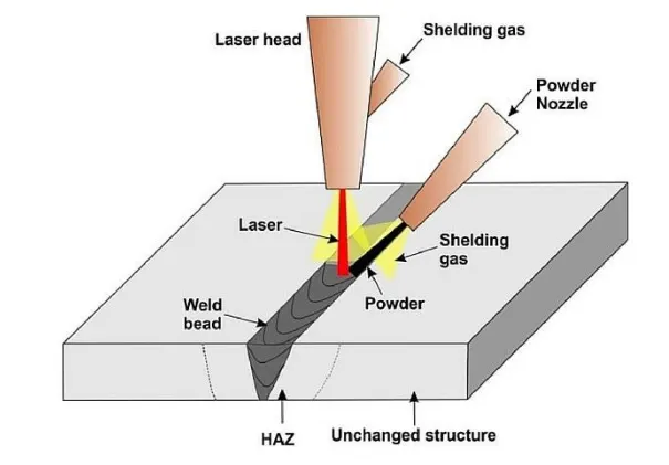
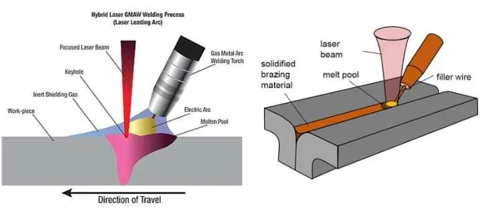
Laser welding operates in two fundamentally different modes:conduction limited welding and keyhole welding.The mode in which the laser beam will intract with material it is welding depends on the power density across the beam hitting the workpiece.
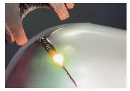
It is not contact process that requires acess to the weld zone from one side of the parts being welded. The weld is formed athe intence laser light rapidly heats thematerial in milliseconds.
The laser beam is a coherent( 1 ph) light of a sinle wavelenfth ( monochromatic).The laser beam has low beam diverance and high energy and it creat heat when it strikes the surface.
Metals used in laser welding are:
1.carbonsteel
2.aluminium
3.titanium
4.low alloys and stainless steels
5.nickle
6.platinum
7.molybednum
INDUCTION WELDING:
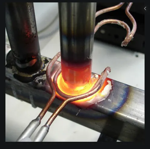
Induction welding is a form of welding that uses electromagnetic induction to heat the workpiece.The welding apparatus contains an induction coil that is energised with a radio frequency electric current.This generates a high frequency electromagnetic fielt that acts as an ellectrically conductive workpiece.In an electrically conductive workpiece ,the main heating effect is resistive heating,which is due to induced current called eddy currents.
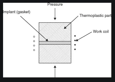
Non magnetic materials and electric insulators such as plastics can be induction welded by implementing them with metallic or ferromagnetic components,called suspectors that absorb the electromagnetic energy from the metallic component and lose their heat to the surroundings by thermal conduction.plastics can also be induction welded by embedding the plastic with carbon fiber .Induced eddy current heat the embeded fiber and lose their heat to the surrounding plastic. Induction welding of carbon reainforced plastic is used in areospace.
BENEFITS:
1. Automated induction logitudinal weldingis a relaiable, hign throughout process.
2.low power consuption and high efficiency of efd induction welding systems reduce cost.
3.Their controlability and repeatability minimize scrap.
4.Their small footprint make them easy to integrate or retrofit into production lines.
APPLICATIONS:
1.Induction welding is used in tube and pipe industry for the longitudinal welding of stainless steels(magnetic and non magnetic),aluminium,low carbon and high strength low alloy(HSLA)steels and many other conductive materials.
2.Induction welding of carbon reinforced plastics used in areospace.
5. 3-2-1 PRINCIPLE:
Fixture must locate correctly a workpiece in a given orientation with respect to cutting tools or measuring device or with respect to other device .locating and clamping are the critical functions of any work holding devices.
A workpiece free in space can freely move in an infinite number of directions.For analysis,this motion can broken down to twelve directional movements or 'degrees of freedom'.
All twelve degrees of freedom must be restricted to ensure proper referencing of workpiece.
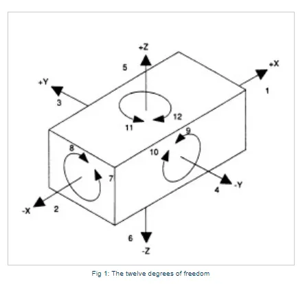
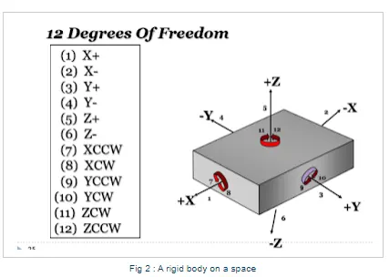
The best and most effective method of part location is reffered as the 3-2-1 principle method.
3 - Three locator blocks to establish part plane.Three locators or supports are placed under the workpiece. The three locators usually positioned on the primary locating surface .This restricts one axial downward movement and 4 radial movements.Together the 3 locators restricts 5 degrees of freedom(dof).
Three pin restricts movements in :
1. -Z
2. CROT- X AXSIS
3.ACROT- X AXSIS
4. CROT- Y AXSIS
5.ACROT- Y AXSIS
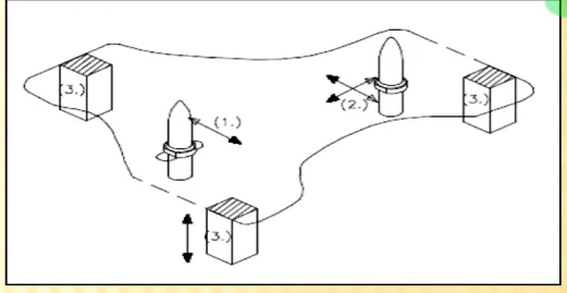
2 - Round locating pin in around hole that defines location in four direction (4-way) perpendicular to the plane previsioly established.This restricts the 4 axial movements.
round locating pin restricts movements in:
6. +X
7. -X
8. +Y
9. -Y
1 - Round locating pin in a slot that deines two of the directions of the other pin ( 2 way). Tis restricts two axial movements.
Round locating pin restricts movement in:
10. +z
11.CROT - Z AXSIS
12.ACROT - Z AXSIS.
6.BODY COORDINATE SYSTEM:
The body coordinate coordinate system has been widely used in the automotive industry for drawing at body parts,products and design.
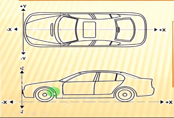
A coordinate system is a reference system consisting of a set of points ,lines and surfaces used to define the positions of points in either two or three dimensions.In general, BCS is also called as carline and bodyline.
X- Longitudinal direction[(fore & after -F/A) or (Front O line - FOL)]
Y- Transverse direction[(cross car-C/C) or (center O line - COL)]
Z- Vertical direction[(up/down) or (bottom O line - BOL)]
The orgin of the body coordinate system(OX) is defined as the front center of the vehicle ,it indicates the length of a car and the coordinate system (OZ) is below its underbody inicates height of a car ,and the coordinate system (OY) its starting point is the center of a car body indicates width of a car.
7.BODY PLANES:
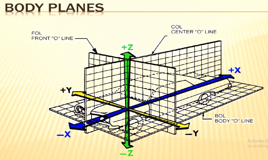
Body planes are the reference planes in an automotive car.These planes are used to define the GD&T of all car parts in a automotive domine.
Body planes are three mutually perpendicular imaginary planes.These are generally considered to be present at the driver position or sometimes at the engine location or at the front of the car depending on the customer.

The measurements from the body planes to the parts are called as bodyline dimensions.
These body planes are called as:
- FOL Front "O" line.
- COL Center "O" line.
- BOL Bottom "O"line.
- The measurements along FOL or X - axsis is called as F/A front after
- The measurements along COL or Y - axsis is called as C/C cross car.
- The measurements along BOL or z - axsis is called as U/DUP down.
BODYLINE DIMENSIONS ARE ESSENTIAL FOR REASONS STATED BELOW:
- It defines excat position of each product in the vehicle with respect to a fixed orgin.
- It ensures flawless design for assembly.
- While desigining lines , all the designs are carried out relative to the bodyline , viz.,fixture,turntables etc.,
- It assists easy location of different parts in vehicle.
- It aims in creating a standardised system.
- It assists in quality checks.