Week 9 - Challenge 2 - Switch Bezel Design
Switch Bezel Design
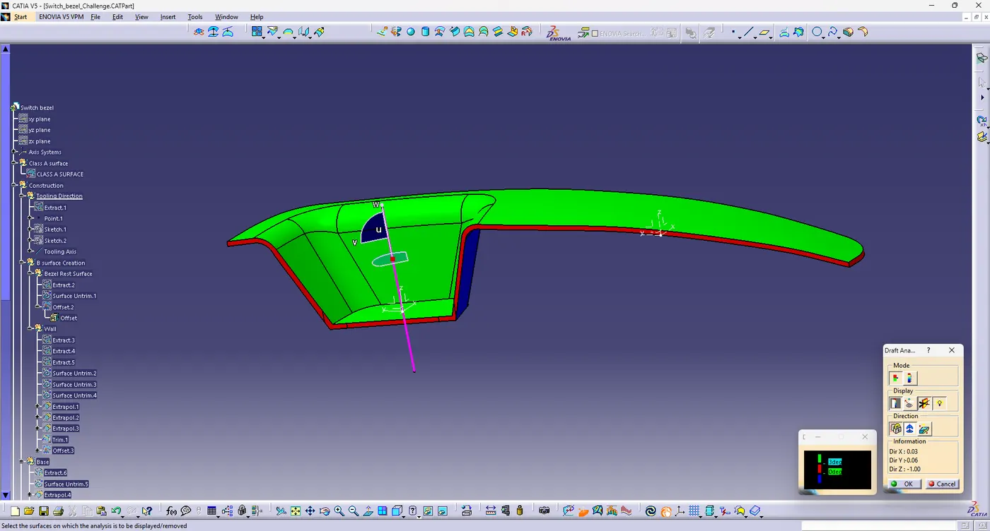
Draft Analysis
When manufacturing any plastic component, a draft angle is incorporated into the design tapering each side from the base to an angle slightly less than 90 degrees. This design feature ensures that the molded part can be easily removed from the mold after the molding process. Without a draft angle, vertical walls at 90 degrees would create a significant friction during ejection due to material contraction as the plastic cools causing damage to the component or the mold.
To address this issue the CAD engineers adhere to the standard practices while designing a plastic mold or a die. This standards dictate the inclusion of draft angle usually ranging from 3 to 10 degrees, to facilitate smooth ejection of the plastic part without compromising the structural integrity or the structural finish of the part.
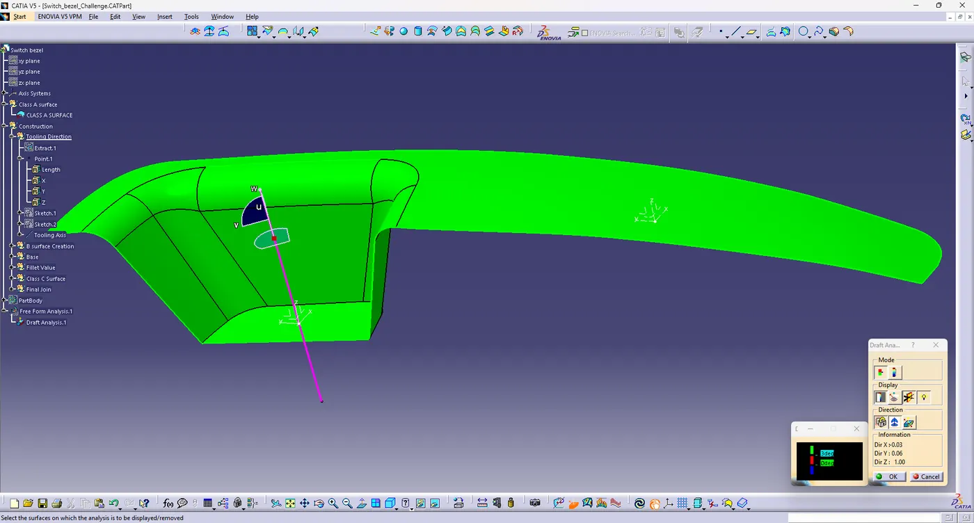
Hence the draft analysis is preformed to the given Class A Surface and it is clearly observed that there is no negative draft angle on the surface.
Tooling Axis Creation:
The tooling axis is a crucial element in the design process, representing a direction along which a molded component is drawn or formed. This axis ensures the finished part can be easily ejected from the mold or the tooling setup. Proper definition of the tooling axis is important to avoid undercuts and ensure smooth material removal without damaging the component or the tool after the manufacturing process is complete.
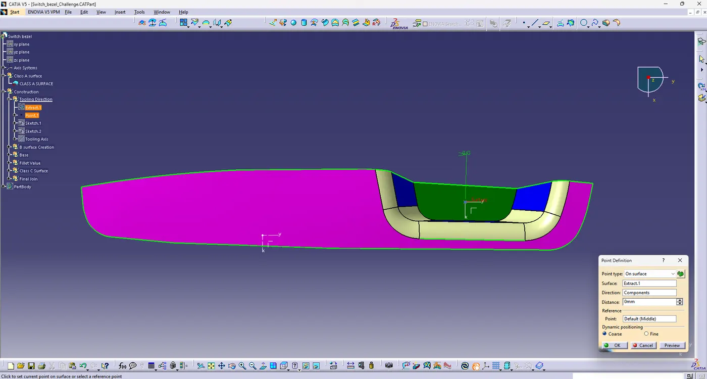
The tooling axis is created for the given Class A Surface.
Creation of tooling axis:
1. Extract the base surface of the given class A surface and create a point at the center of the extracted surface.
2. Then create two sketches on two planes by taking the cross section of the given surface on particular plane.
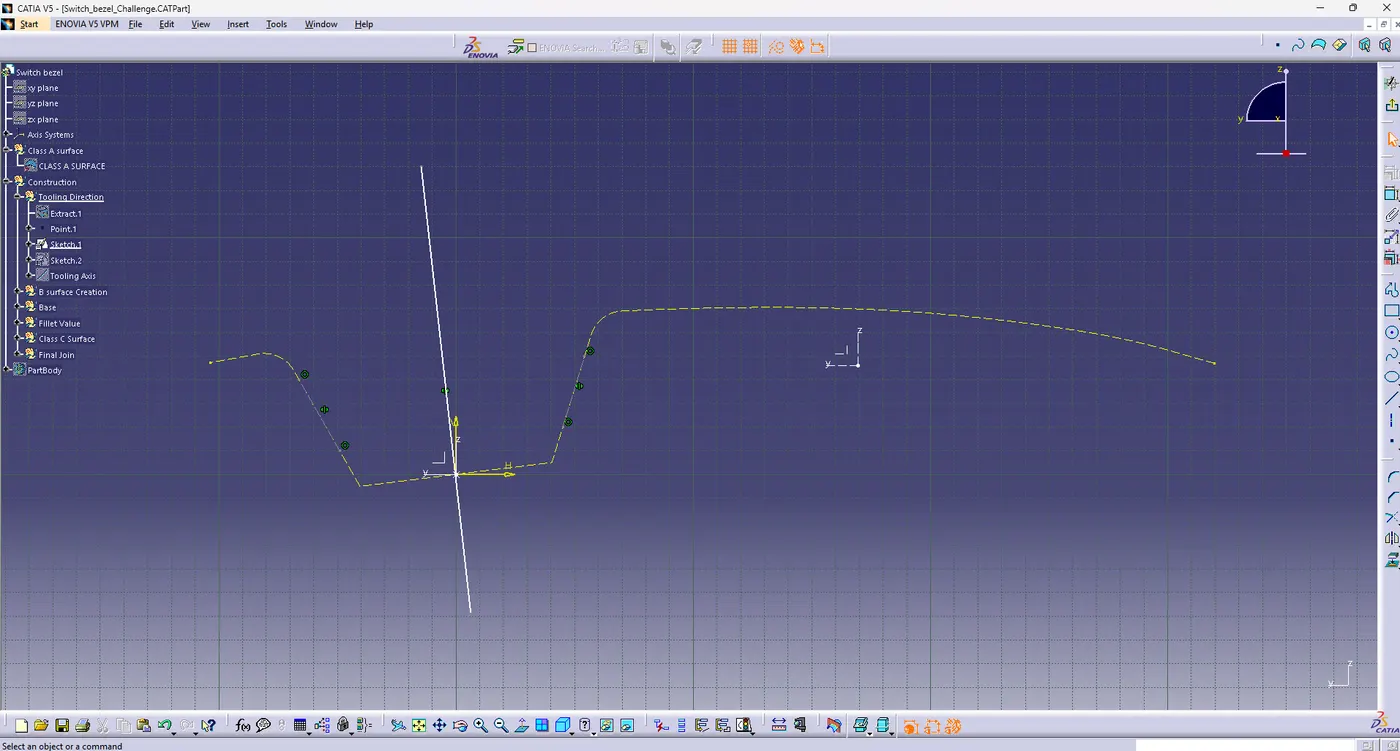
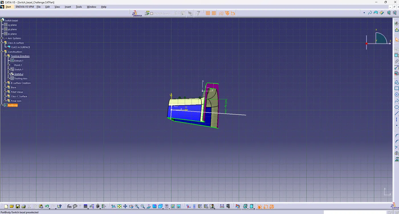
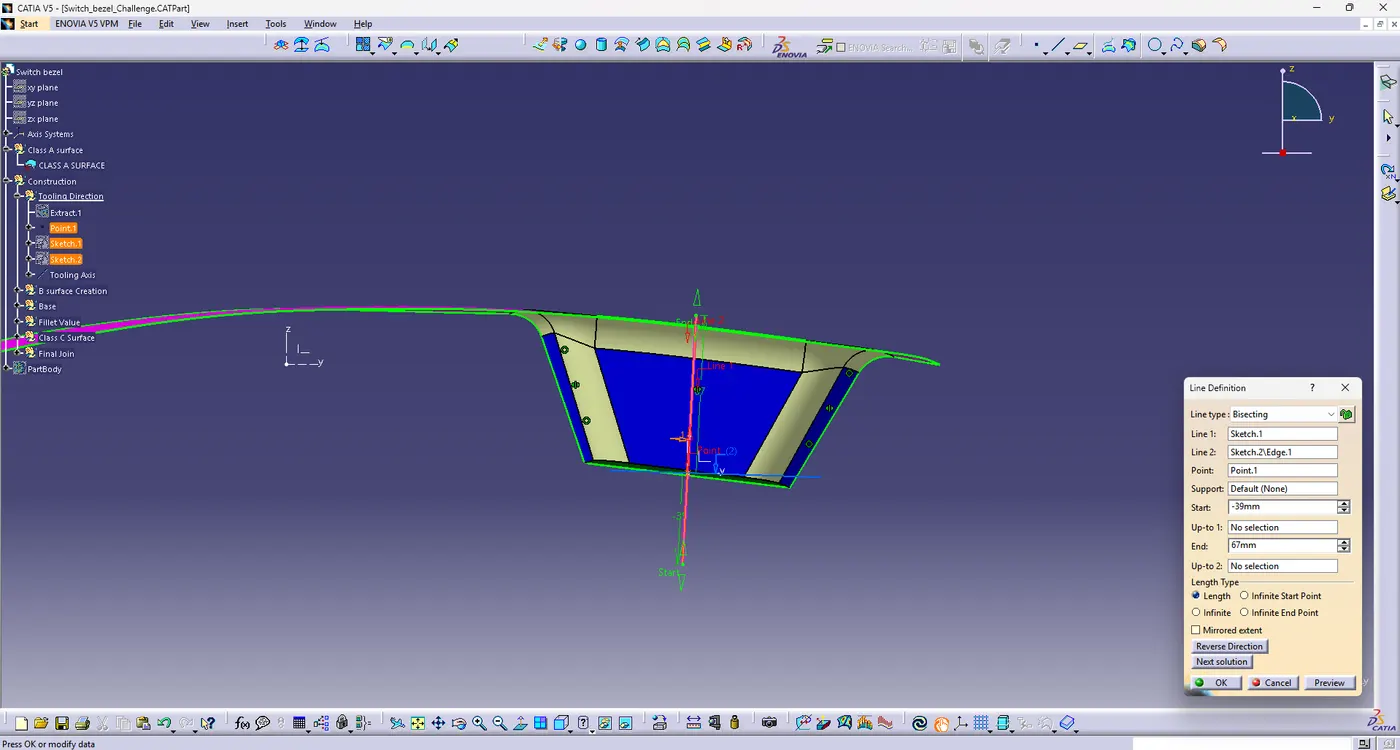
3. Tooling axis is created from the two lines sketched in two planes using the bisecting method.
Creating class B and Class C Surface:
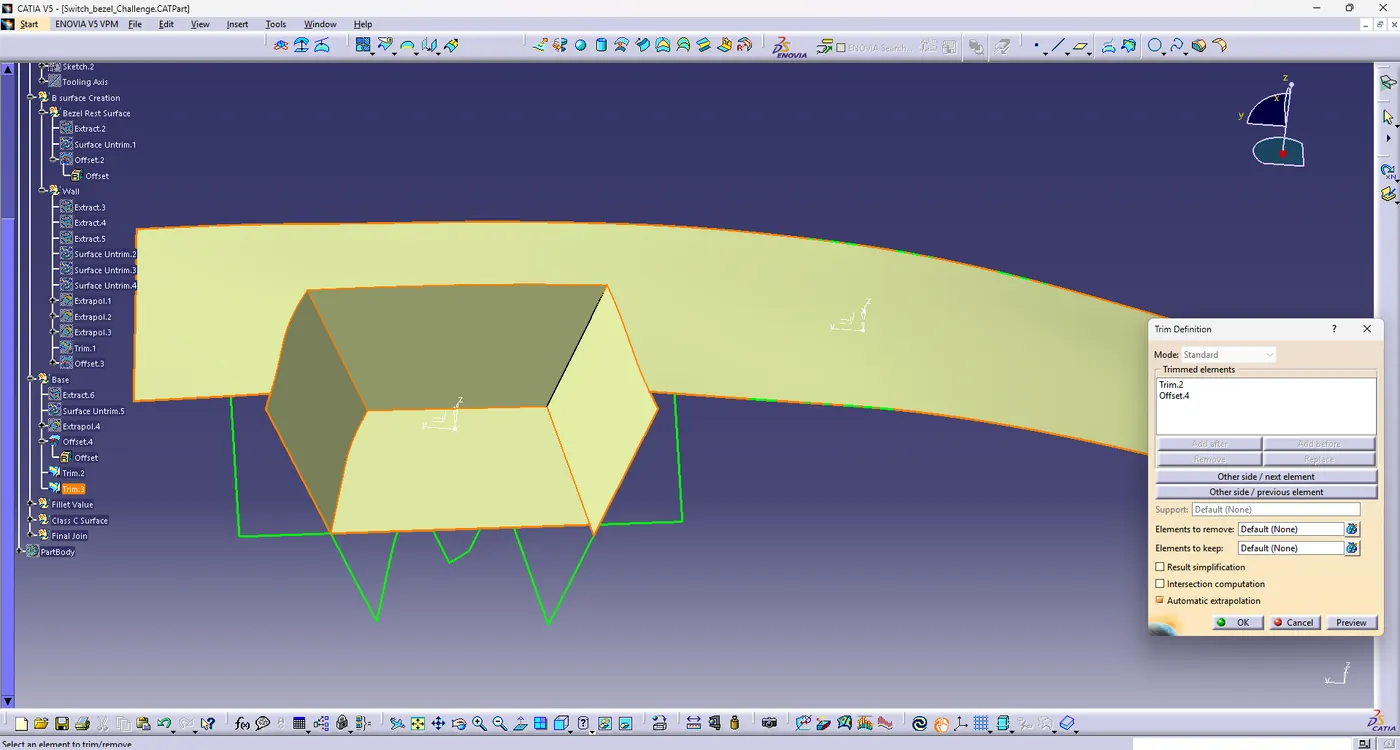
Extracting the class A Surface without fillets and then untrimming them, extrapolating them to join them and then offsetting the extracted surfaces for the thickness of the part ie.. 2.5 mm forms class B surface.
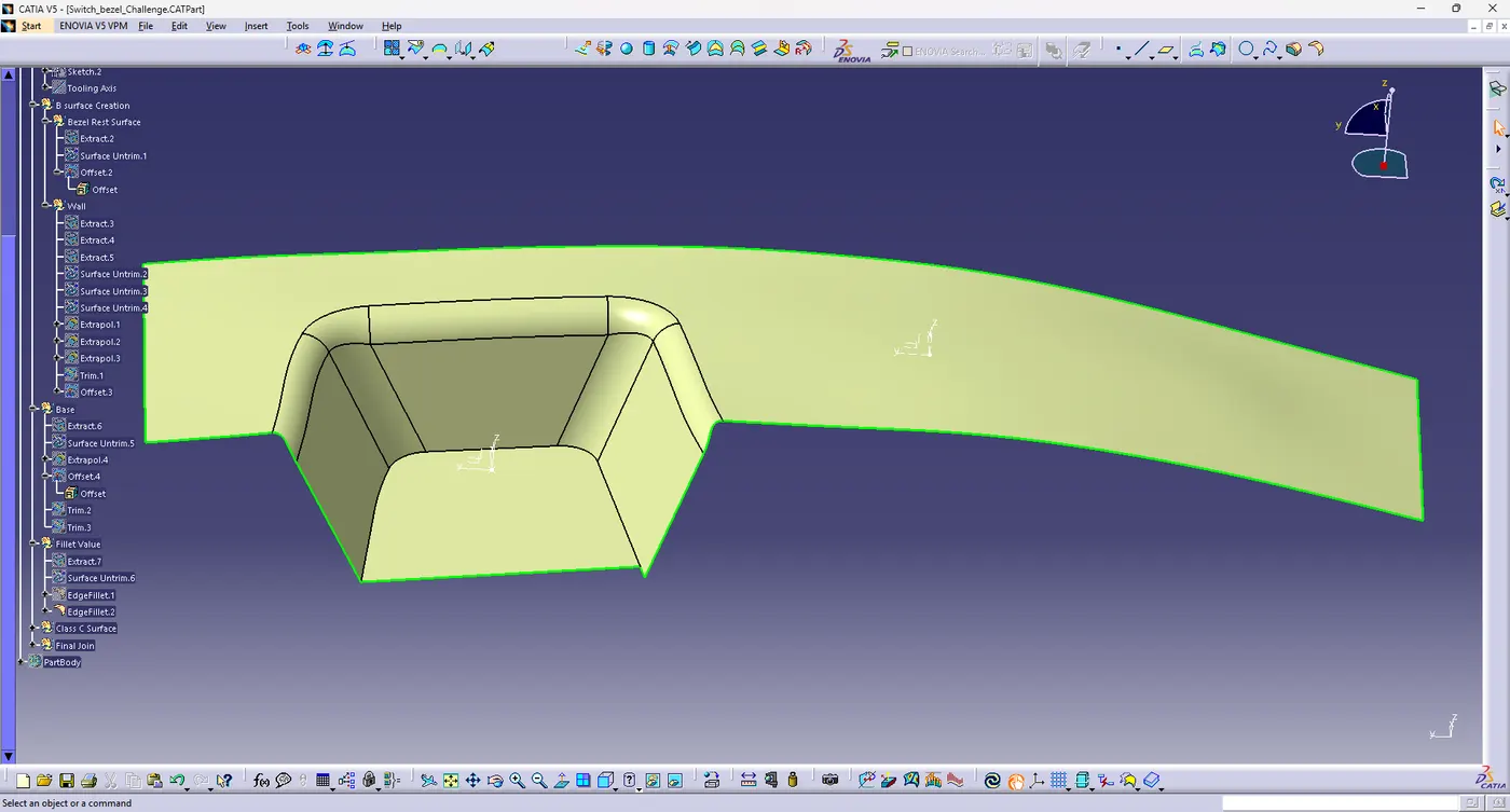
Then fillet the required edges to the dimension based on the fillet on class A Surface and the thickness of the part calculate the required fillet radius accordingly and then apply fillet on the B Surface.
Class C Surface Creation:
By Extracting the boundary of class A Surface , and using the sweep command the class C Surface is extracted.
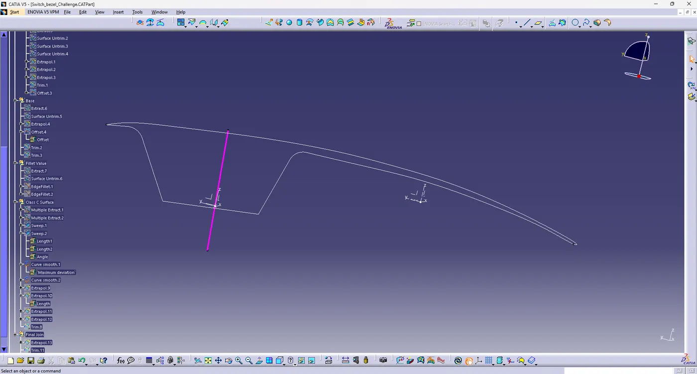
Using the smooth curve option a smooth curve option a smooth curve can be obtained by sweeping the curve in the direction of the tooling axis.
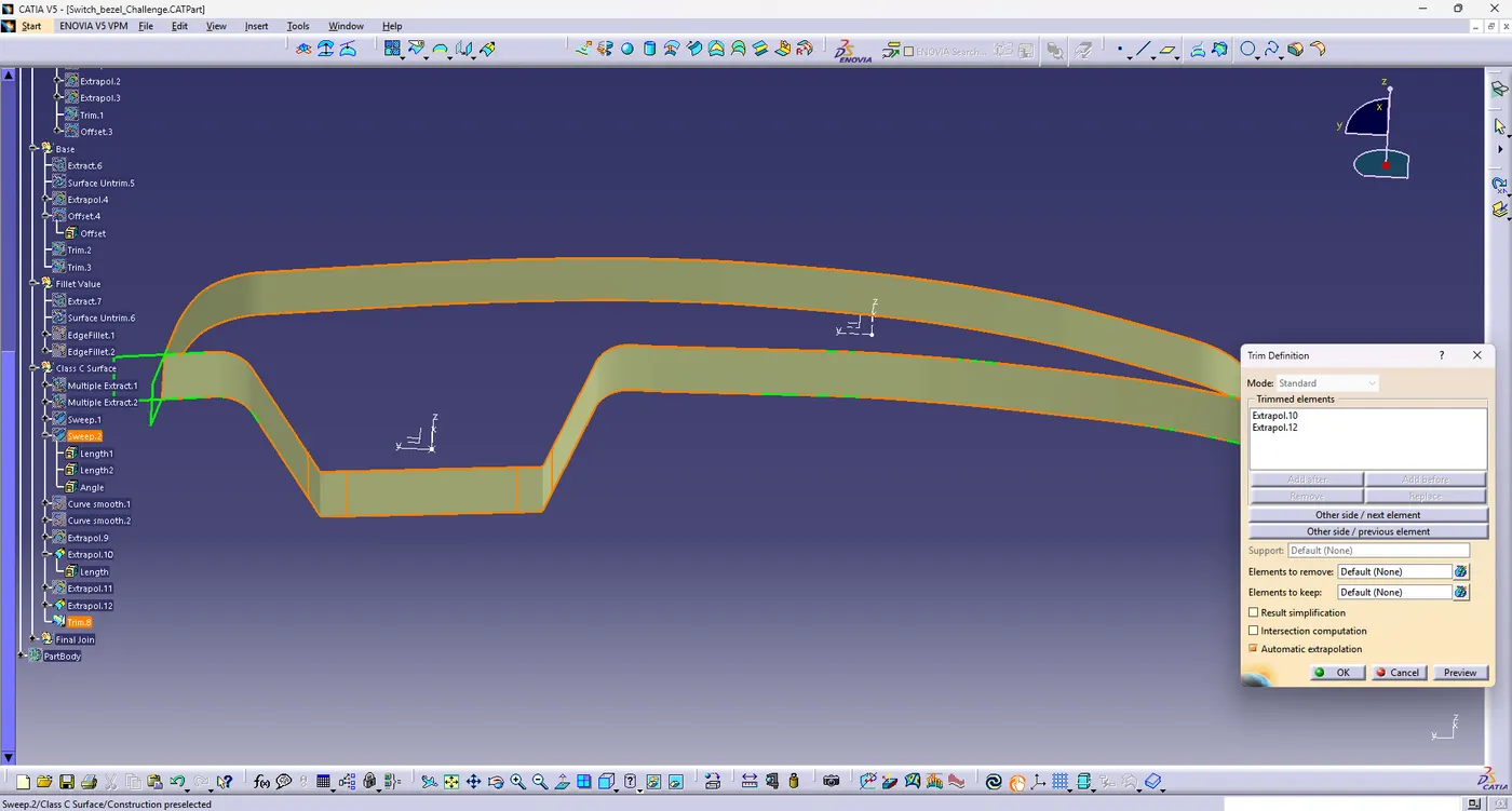
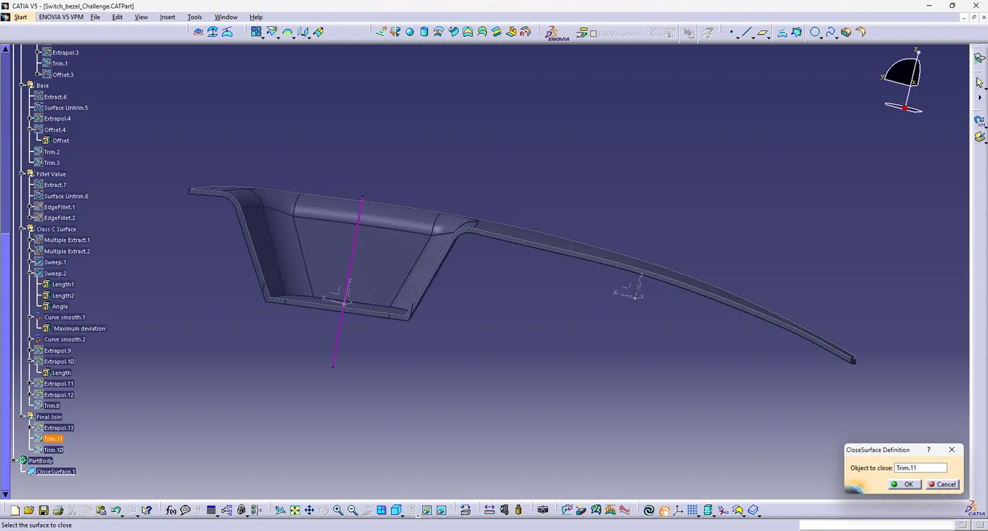
Once the C Surface is created. Then Class A and Class C surfaces are joined together and then the combined surface is used to trim the B Surface to create a closed surface.
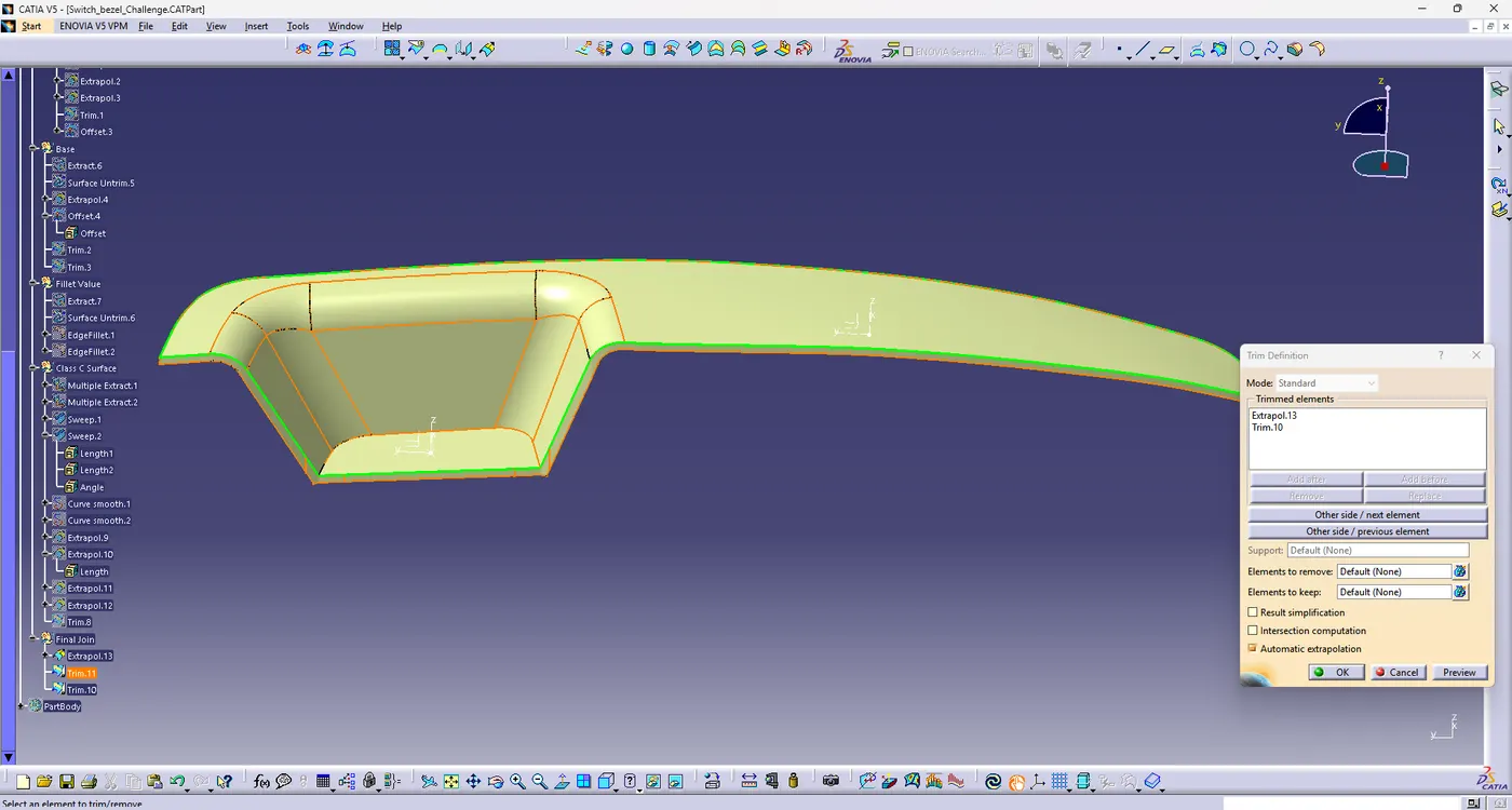
Once the closed body is formed then the draft analysis is performed to the closed surface.
Once the closed surface is done then we move to the part workbench and use the surface based features option to select the closed surface feature and then the closed surface is converted to part body.