Week 9 - Challenge 2 - Switch Bezel Design
Week 9 - Challenge 2 –
`Switch Bezel Design
A car switch bezel is a trim panel that surrounds the switches and controls on a car's dashboard or door panel. It is typically made of plastic or metal and is designed to be both functional and stylish.
Function
The main function of a car switch bezel is to protect the switches and controls from damage. It also helps to direct the driver's attention to the controls and makes them easier to operate. In addition, the bezel can help to improve the look and feel of the car's interior.
Types
There are two main types of car switch bezels:
- Hard bezels are made of a hard plastic or metal and are typically used in older cars.
Hard bezel switch bezel
- Soft bezels are made of a soft plastic or rubber and are typically used in newer cars.
Soft bezel switch bezel
Soft bezels are more comfortable to operate and can provide a more luxurious feel. They are also less likely to scratch or break.
Materials
Car switch bezels are typically made of one of the following materials:
- ABS plastic is a common choice for bezels because it is strong, durable, and inexpensive.
ABS plastic
- Polypropylene is another strong and durable plastic that is often used for bezels.
Polypropylene
- Metal bezels are typically made of aluminum or chrome. They are more expensive than plastic bezels, but they are also more durable and can provide a more luxurious look.
Metal bezel
Design
The design of a car switch bezel is typically determined by the following factors:
- The type of switches and controls that the bezel will surround.
- The location of the bezel on the car's dashboard or door panel.
- The overall design of the car's interior.
Bezels can be simple or complex, depending on the car's design. Some bezels are simply flat panels with holes for the switches, while others are more sculpted and may include decorative elements.
Installation
Car switch bezels are typically easy to install. They are usually held in place with clips or screws. In some cases, it may be necessary to remove the door panel or dashboard trim panel in order to install a new bezel.
Cost
The cost of a car switch bezel can vary depending on the material, design, and brand. Bezels for older cars can be purchased for as little as $5, while bezels for newer cars can cost upwards of $100.
Maintenance
Car switch bezels do not require much maintenance. They can be wiped down with a clean cloth to remove dust and dirt. If the bezel is scratched or damaged, it may need to be replaced.
Steps in detail that are involved to create switch bezel are as follows
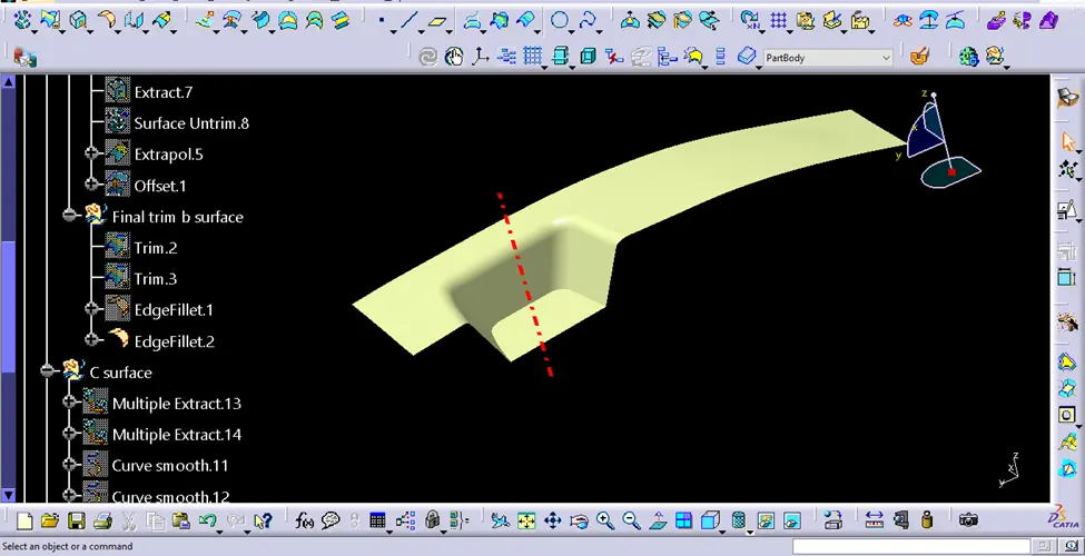
The first geometrical set was created with the name tooling axis and a sketch was created taking the reference of the two planes. The sketch involved two lines drawn in the the planes and then bisector of the two lines was created which was the main tooling direction.
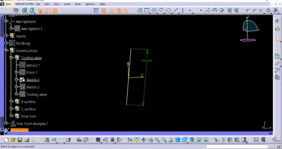
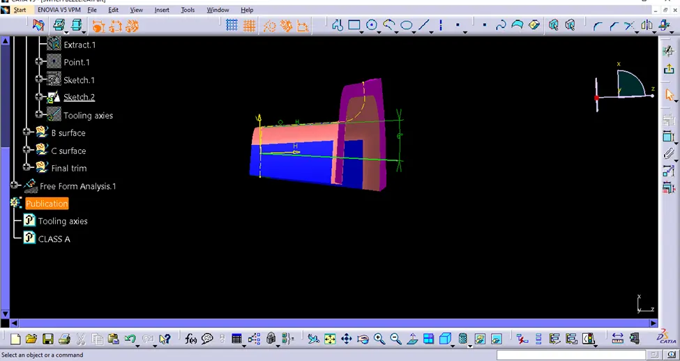
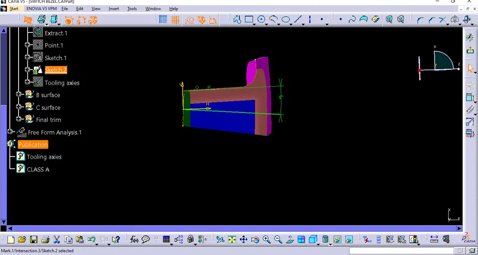
The tooling axis is shown with dotted red line.
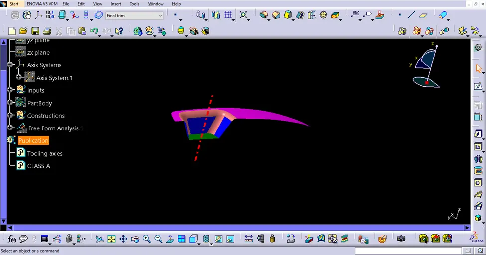
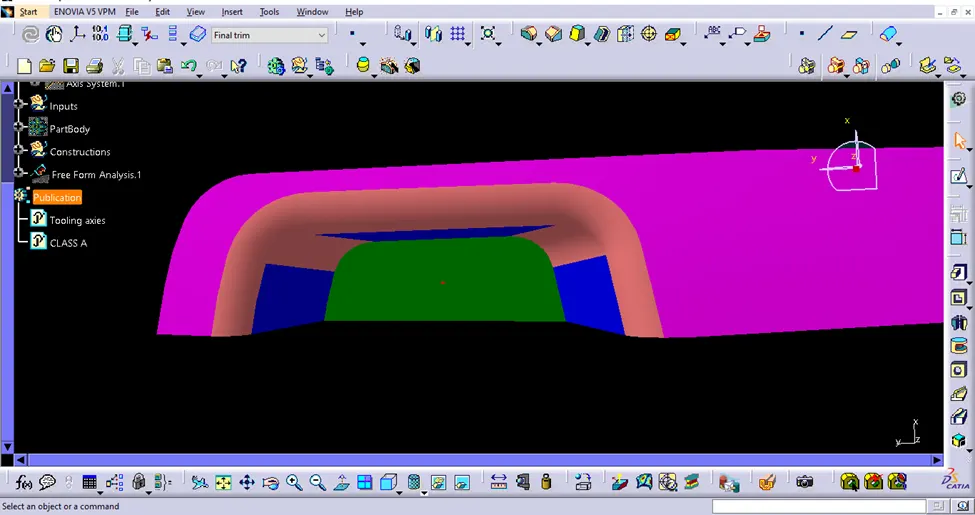
A new geometrical set with the name B surface was made and the top, side and bottom surfaces were extracted.
The same surfaces were untrimmed and later extrapolated to carry out trim command in between them perfectly.
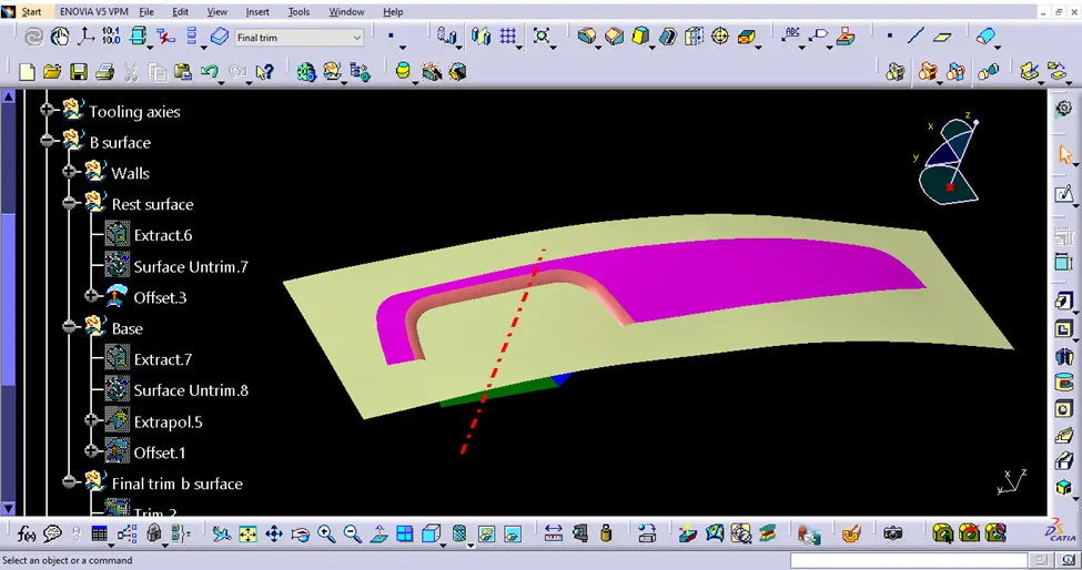
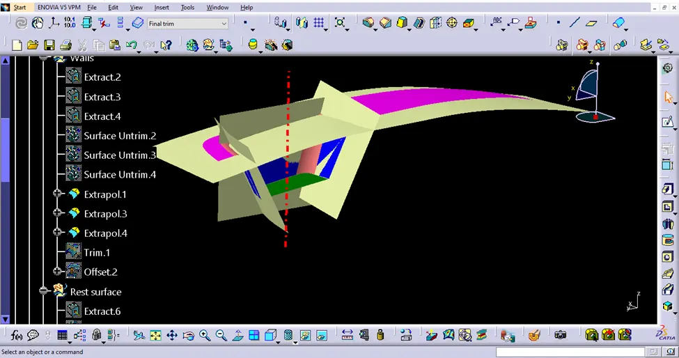
After getting the surfaces, it was trimmed and made to form a single surface.
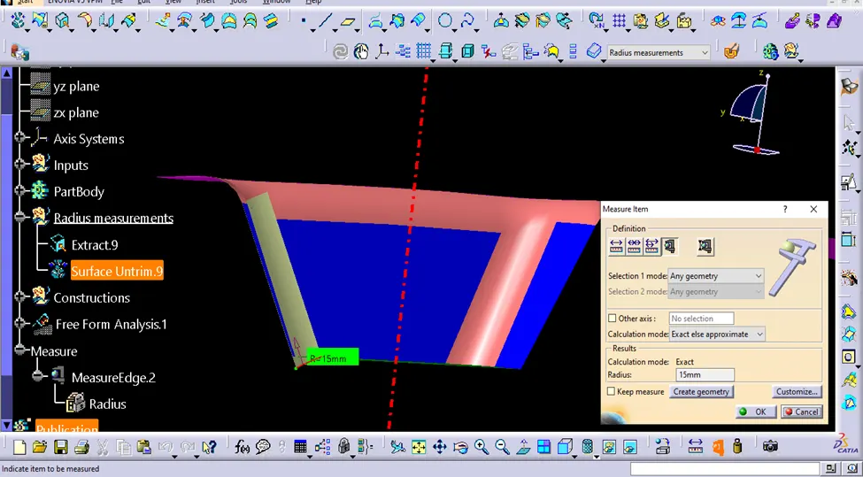
The fillet radius was obtained by measuring the same and later it was given the B surface at the same region as seen on A surface. The value given for fillet was radius - thickness i.e. 15-2.5=12.5mm and 14-2.5=11.5mm.
A new geometrical set with the name C surface was created.
Multi-extract command the boundary was created on the A and B surface.
It was made into a surface by using swept option and the tooling axis was considered and also the draft angle=3degrees.
The surface was having too many marks so smooth curve command selected and replaced by the the above curve to obtain a smooth surface without marks.
Surface A and C were joined by giving 0.003mm as merging distance.
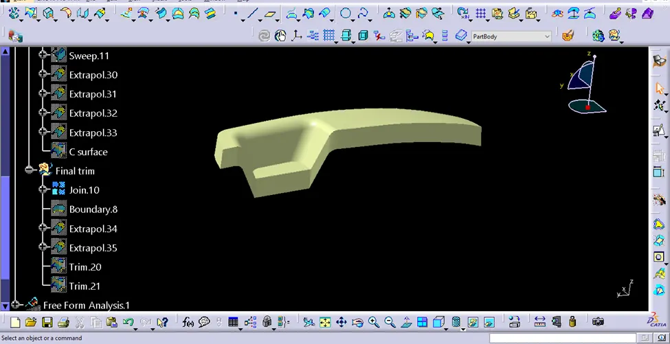
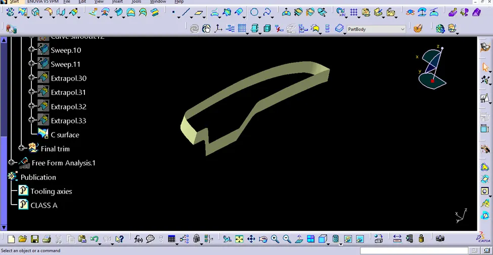
The last geometrical set was created and was named Final join. Surface A and C were joined to form a single surface and in the same manner surface B was trimmed taking into consideration the above mentioned surface to get the final part.
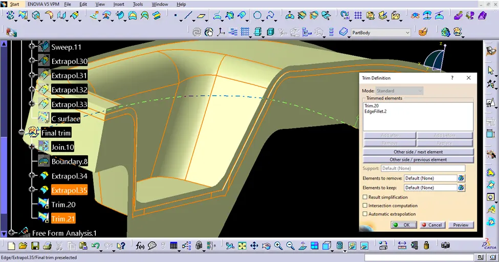
The window was switched to part design where the hollow part was turned into a solid part by using closed surface command.
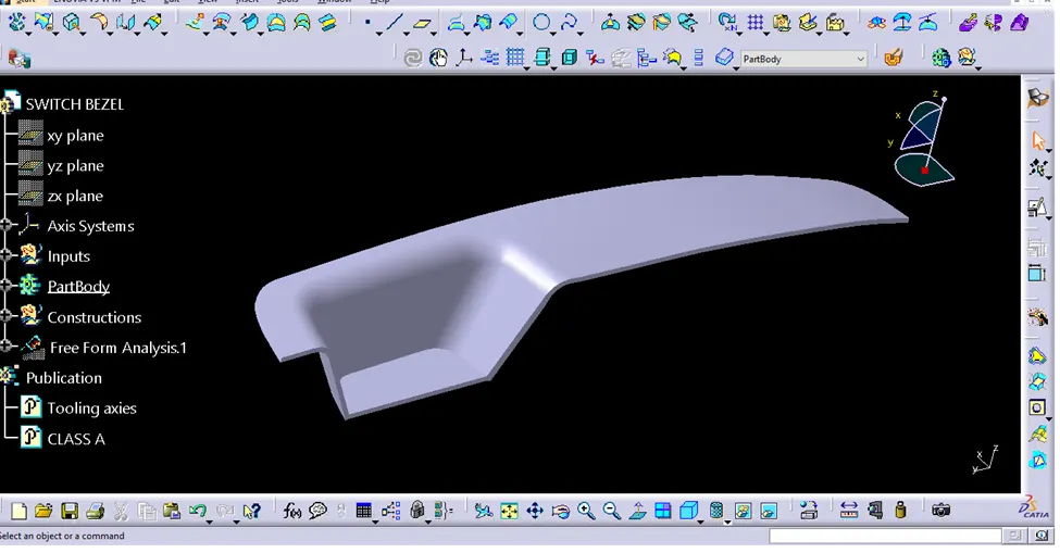
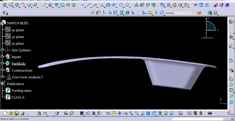
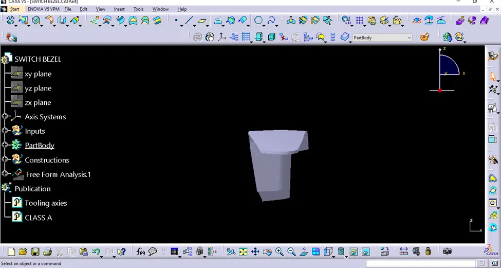
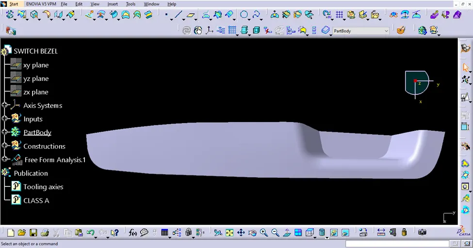
The same part is shown in different views below:-
ISOMETRIC VIEW
FRONT VIEW
SIDE VIEW
TOP VIEW
DRAFT ANALYSIS
Draft analysis in CATIA V5 is a process that is used to check whether a part can be easily removed from a mold or die. This is important because if a part cannot be easily removed, it can damage the mold or die and cause the part to be defective.
To perform a draft analysis, you will need to create a 3D model of the part in CATIA V5. Once you have created the model, you will need to define the draft angle. The draft angle is the angle between the surface of the part and the direction of the mold or die. The draft angle should be large enough so that the part can be easily removed, but not so large that it weakens the part.
Once you have defined the draft angle, you can run the draft analysis tool. This tool will check the entire surface of the part and will highlight any areas where the draft angle is too small. You can then adjust the model to increase the draft angle in these areas.
In addition to the draft angle, you will also need to consider the parting line. The parting line is the line where the mold or die will split open. The parting line should be positioned so that it does not interfere with the removal of the part.
Draft analysis is an important step in the design process for any part that will be manufactured using a mold or die. By performing a draft analysis, you can ensure that your part can be easily removed from the mold or die and that it will not be damaged.
Here are some of the benefits of using draft analysis in CATIA V5:
- Reduced manufacturing costs: Draft analysis can help to reduce manufacturing costs by preventing parts from being damaged during demolding.
- Improved part quality: Draft analysis can help to improve part quality by ensuring that parts are free from defects caused by demolding.
- Increased design efficiency: Draft analysis can help to increase design efficiency by identifying potential problems early in the design process.
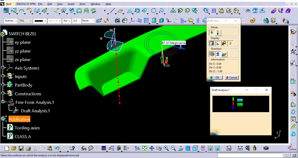
· Draft analysis was carried out by switching to material view.
· The compass was relocated to the new position by aligning with the tooling axis and locked.
· By taking the pointer on the part which showed a red cross, a click on the same location gave the result.
· There were some region with less than 3degree value which was shown by red color.
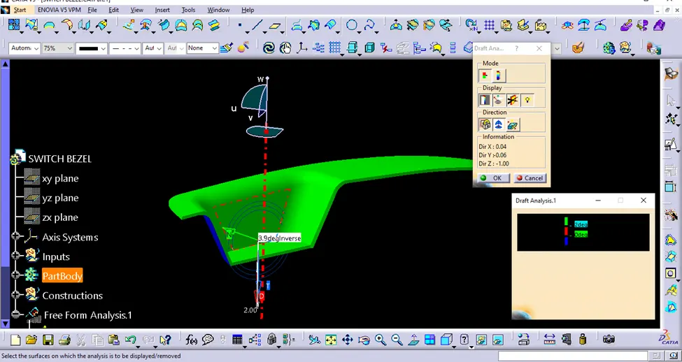
The value was changed to 2.9degree and the part turned into green which states that the part is toolable and produceable.
Conclusion:
If you are designing a part that will be manufactured using a mold or die, I highly recommend that you perform a draft analysis in CATIA V5. It is a valuable tool that can help you to save time, money, and improve the quality of your parts.