Week 9 - Challenge 2 - Switch Bezel Design
Aim:
To create the Switch Bezel Plastic component through the given Class-A surface. To begin with, the tooling axis for the given Class-A Surface should be created meeting the requirements of the draft angle and at the end perform the Draft analysis on the model.
Take the Thickness of the component to be 2.5 mm
INTRODUCTION:
A switch bezel panel is nothing but a part which consists of the switch panels for the power windows and also has some place to rest the passenger’s hand on it. It is assembled on the main door trim panels.
In this project, Switch Bezel panel is designed using Catia v5. I received input as Class A Surface. I Check the direction to eject the tool based on the component design. Later I checked whether all faces that intersected will clear the direction based on the tooling axis. I started working on the Draft Analysis tool to check if our tooling direction clears the path for easy removal of material from the tool. After that, I go class B creation using Advance tools from the surface followed by class C creation using the sweep command. after design A B C class surface, converting close surface into solid inside the part workbench
DESIGN SURFACE:
CLASS A SURFACE:
Class-A surface means visible surface. It gives the aesthetic of the component which is created by the styling team and gives to the part design engineer to create the part with all engineering aspects.
CLASS B SURFACE:
Class-B surface means thickness of a part it is not visible and is inside part. In other words, Class-B surface is a surface below a certain thickness from the class-A surface. This is the surface that contains engineering aspects of a model.
CLASS C SURFACE:
Surface that joins class-A and class-B surfaces is class-C surface. Class C is often specified for interior surfaces not readily visible, surfaces that will be covered by another part when assembled
Given Class A surface:
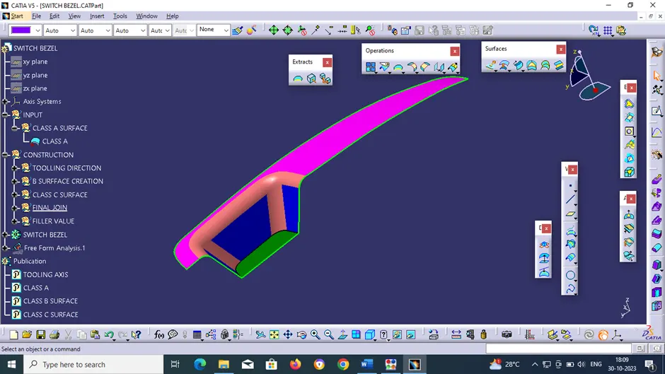
Procedure for creating Tooling Axis:
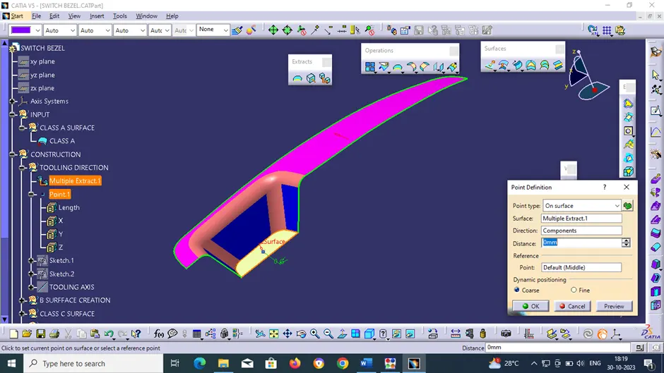
- o A Reference Point is created along the Surface zero and new Axis system is created
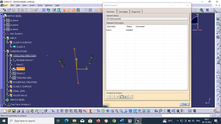
- o The X Direction along the Class A and Y direction along the Class A were used to create Tooling direction
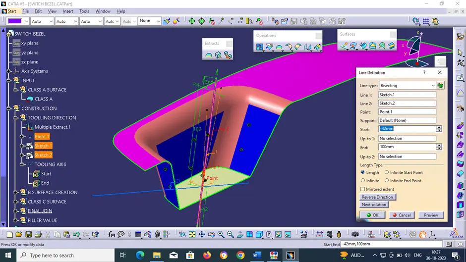
- o Finally, the Tooling axis is created by bisecting the two lines and it is published. Class A Surface as input using surface operation commands Class B is developed
- o The tooling Axis determines the direction of Class C boundary swept with draft direction.
- o When viewing from tooling direction normal all the parts that are drafted should be visible so it gives a rough idea to determine product manufacturing in Injection moulding.
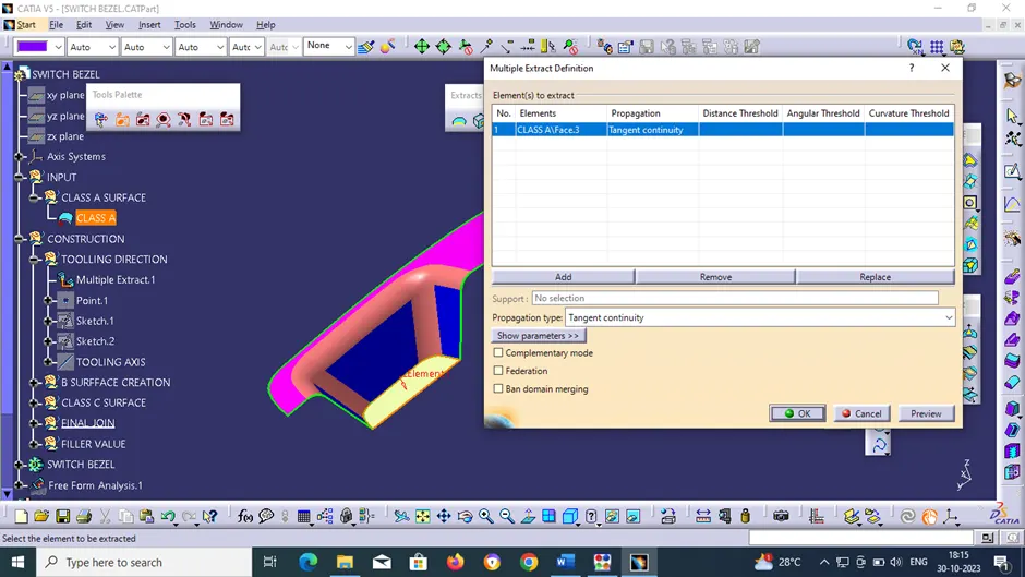
Multiple Extract 1:
Point 1:
Sketch 1:
Sketch 2:
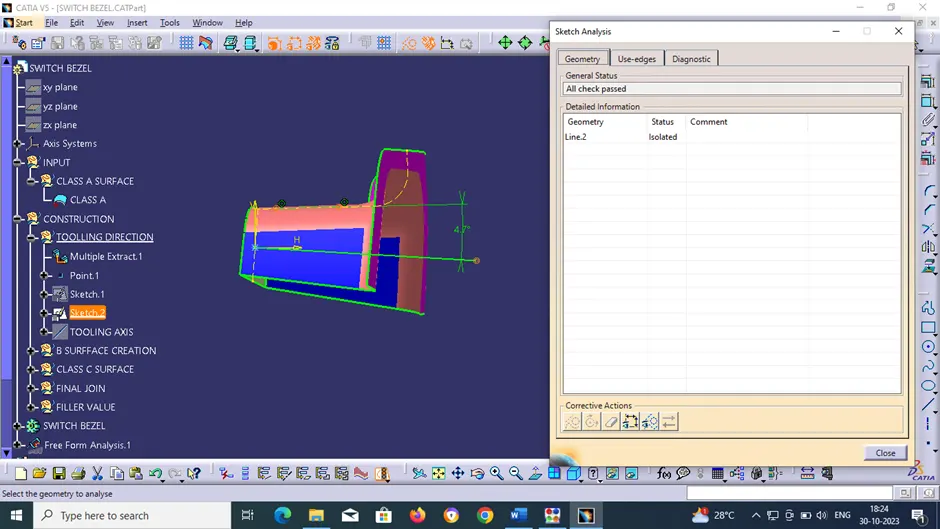
Tooling Axis:
Procedure for creating B surface:
- o The next step is to design B surface for the input which is usually the surface where all engineering aspects and support creations are done.
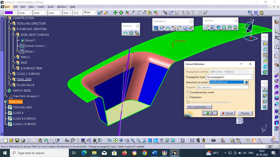
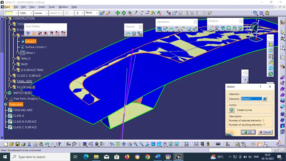
- o The B surface Creation is performed using surface operations in CATIA which is an offset from Class A with dimension proportional to the thickness of the part
- o In Switch bezel the B surface is offset 2.5mm from the input which is the thickness of the part
- o The B surface is an extrapolated surface compared to A surface and forms the bottom skin of the part.
B Surface creation:
Bezel Reset Surface:
Extract 1:
Surface Untrim 1:
Offset 1:
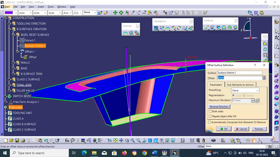
Walls:
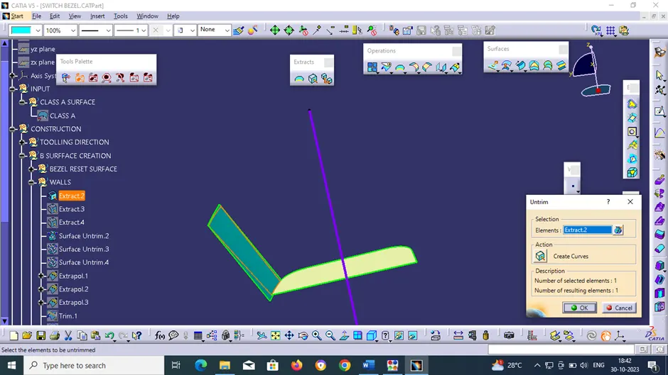
Extract 2:
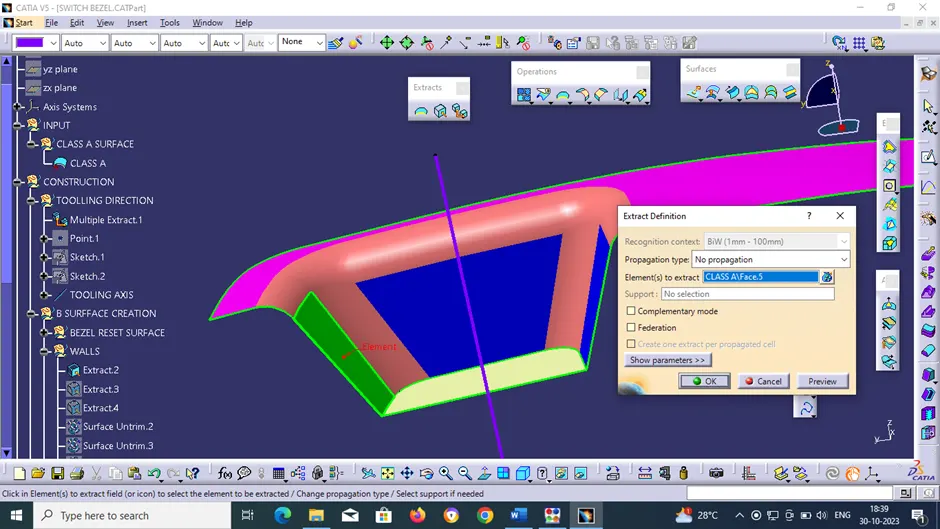
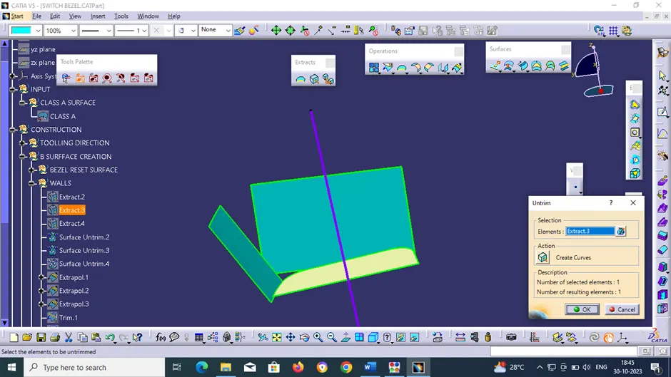
Extract 3:
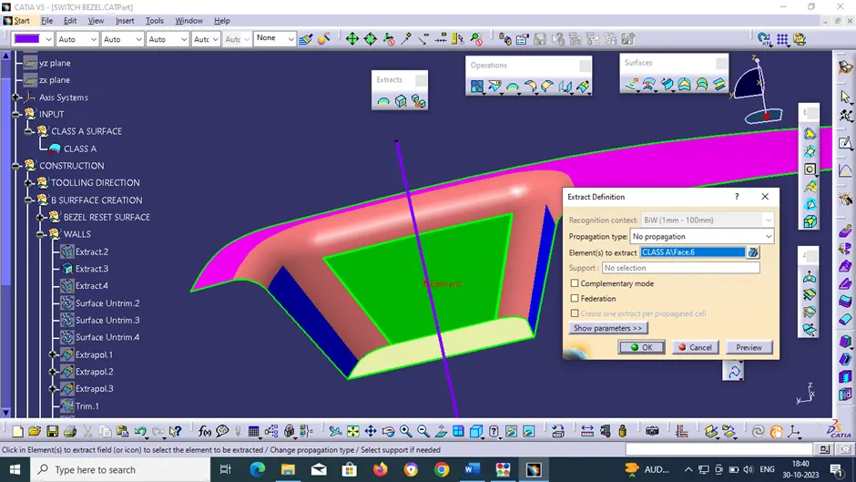
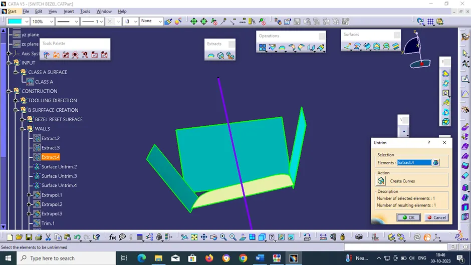
Extract 4:
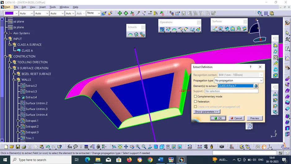
Surface Untrim 2:
Surface Untrim 3:
Surface Untrim 4:
Extrapolate 1:
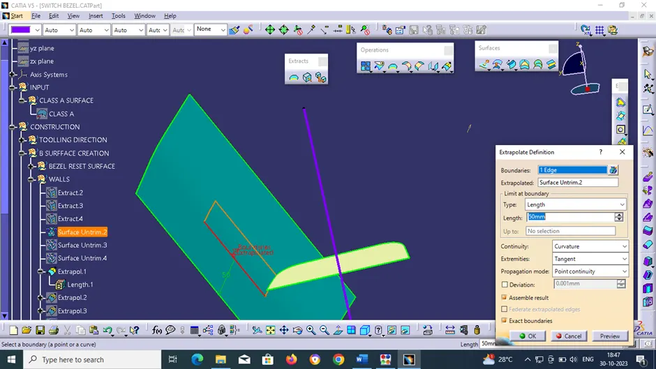
Extrapolate 2:
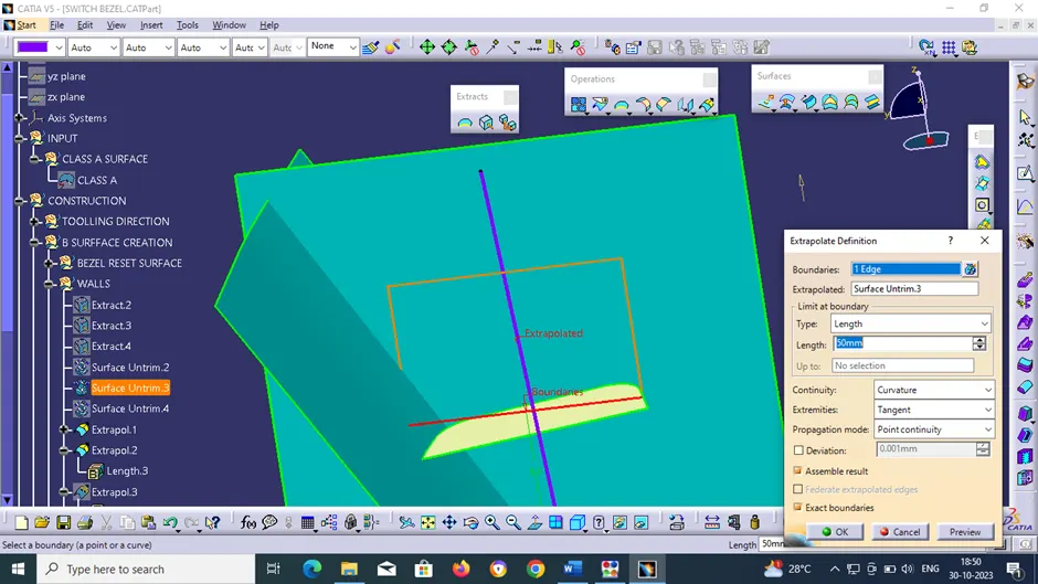
Extrapolate 3:
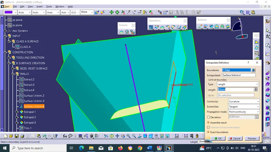
Trim 1:
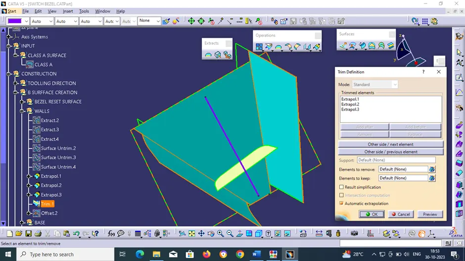
Offset 2:
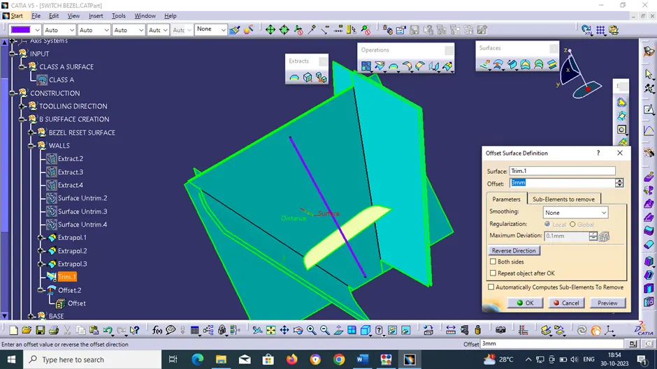
Base:
Extract 5:
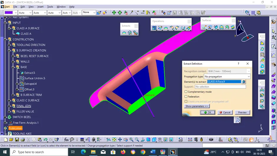
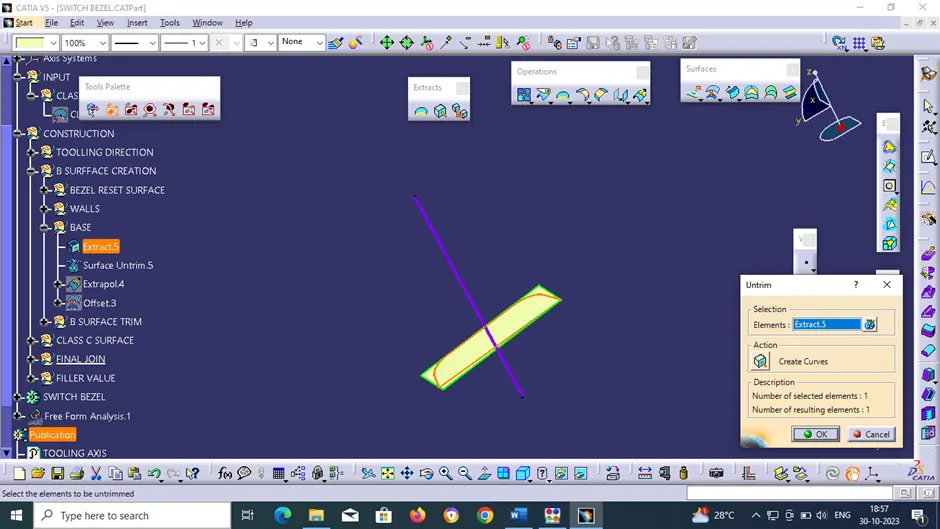
Surface Untrim 5:
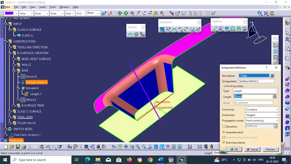
Extrapolate 4:
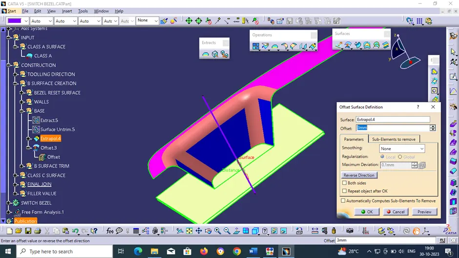
Offset 3:
B Surface Trim:
Trim 2:
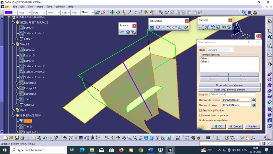
Trim 3:
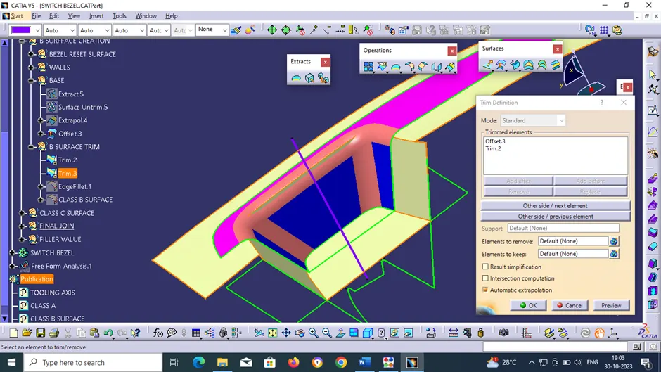
Edge Fillet 1:
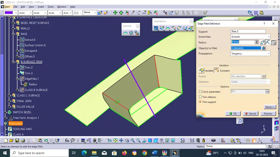
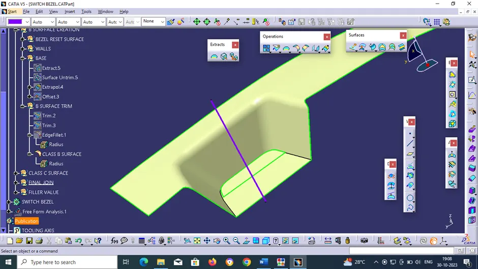
Class B Surface (Edge Fillet 2):
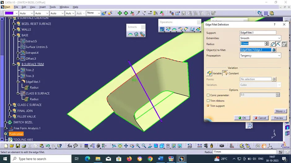
We get
Procedure for creating C surface:
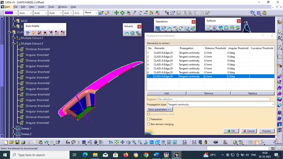
- o The Next step is to from the C surface which is an intermediate surface between A and B and is used to give the closed surface appearance to the design
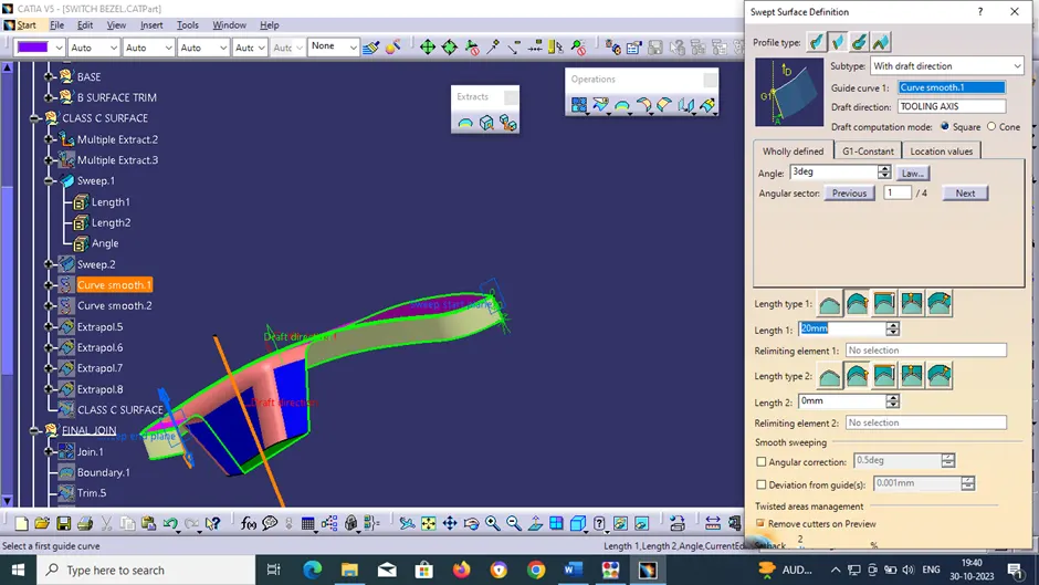
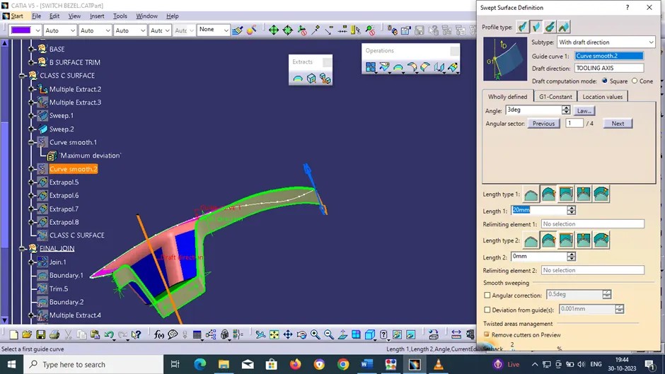
- o The C Surface is swept using the profile as boundary line of Class A which is the Guide curve with a subtype along draft direction.
- o The Direction of the sweep is the tooling direction formed earlier
- o The draft angle for the sweep operation is provided which is 3 Degree and surface is swept for length above the thickness of the specified part
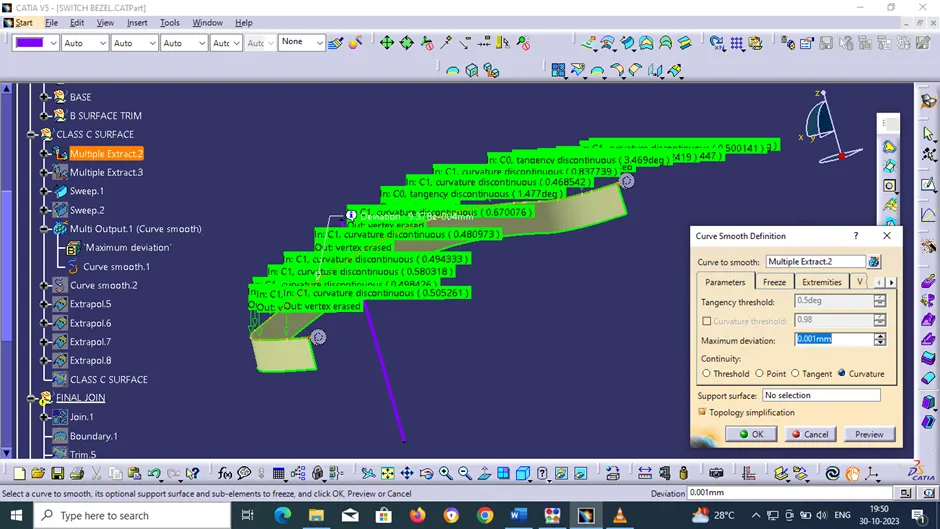
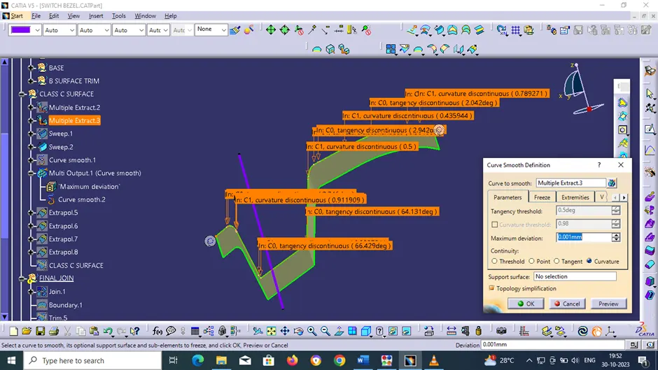
- o The C surface is refined using smooth Curve options to remove the complexity and patches along the swept surface
- o Finally, the Class A and Class C surfaces are joined together and connexity of surfaces should be less than 0.003mm and the surfaces are merged.
Class C Surface:
Multiple Extract 2:
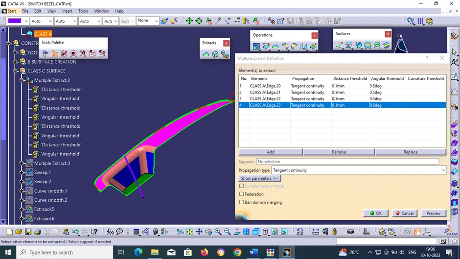
Multiple Extract 3:
Sweep 1:
Sweep 2:
We get
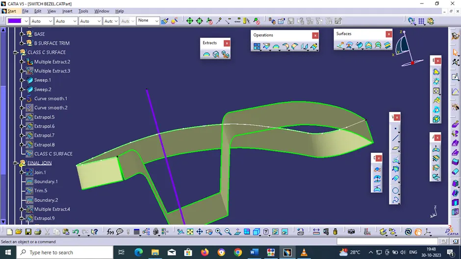
Curve Smooth 1:
Curve Smooth 2:
Extrapolate 5:
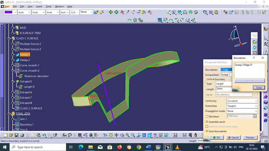
Extrapolate 6:
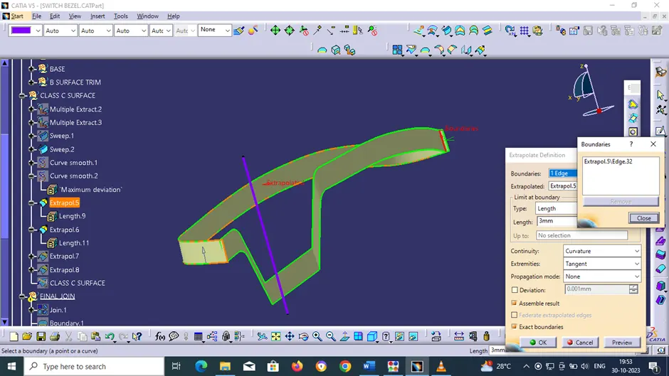
Extrapolate 7:
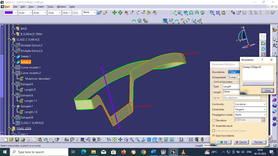
Extrapolate 8:
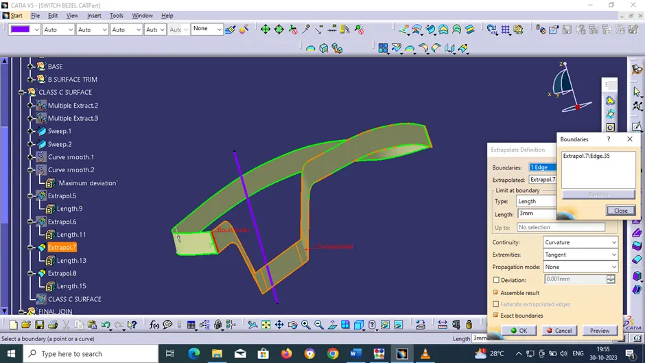
Class C Surface (Trim 4):
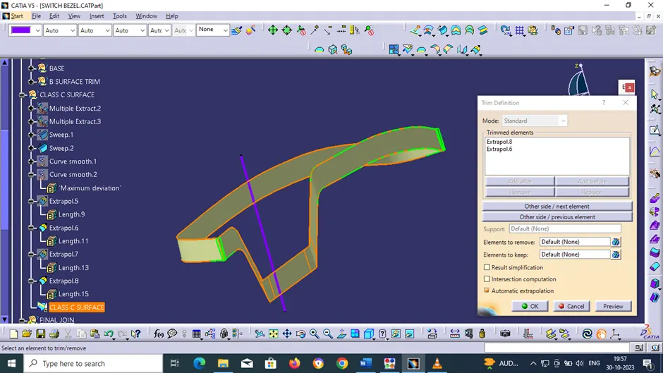
Final Trim and joining:
Join 1:
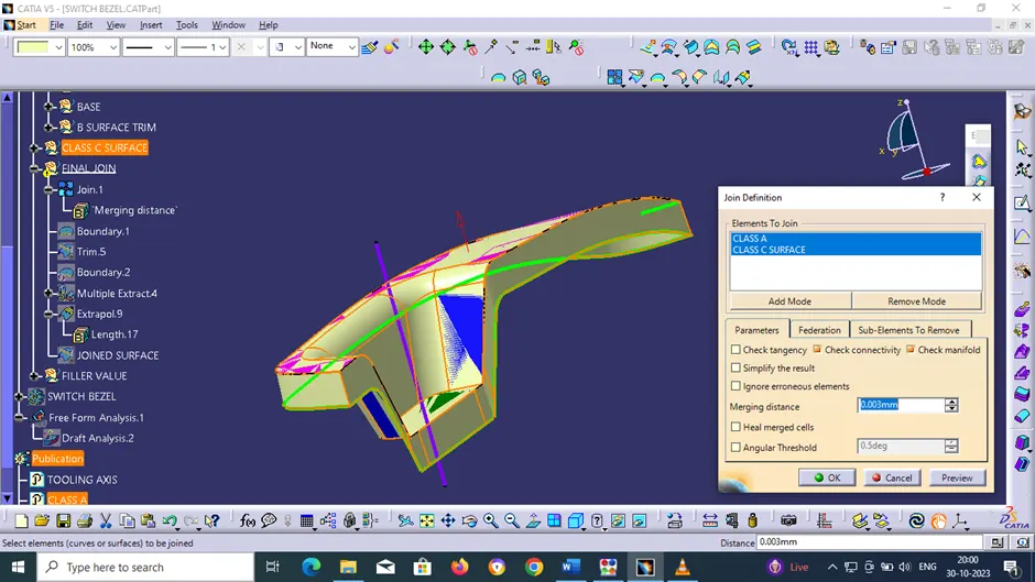
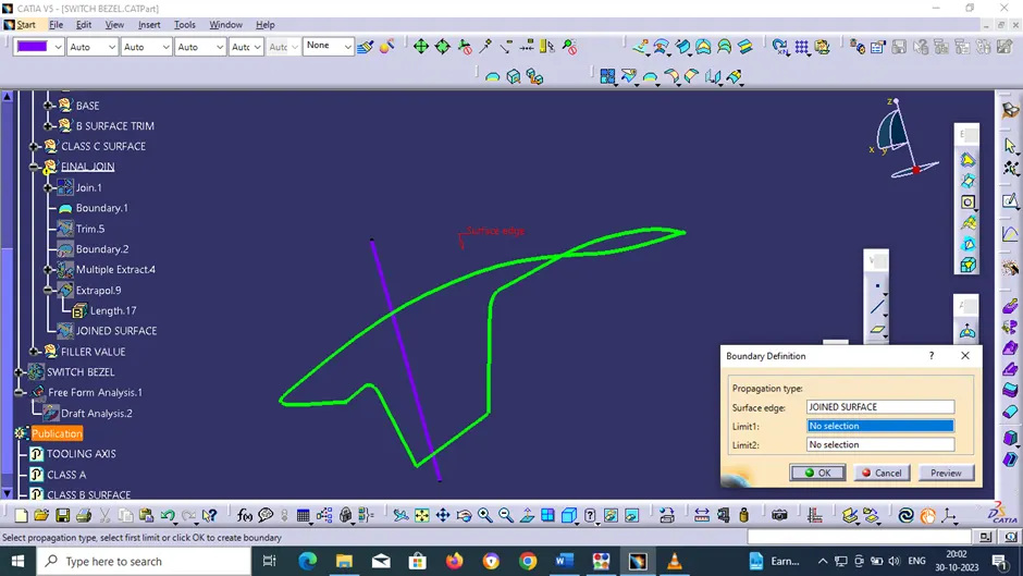
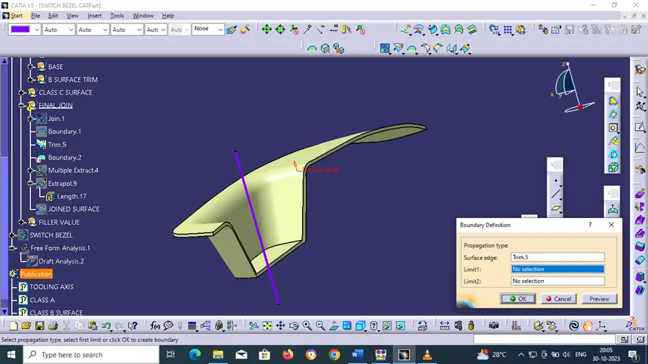
Boundary 1:
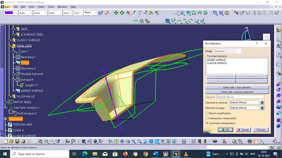
Trim 5:
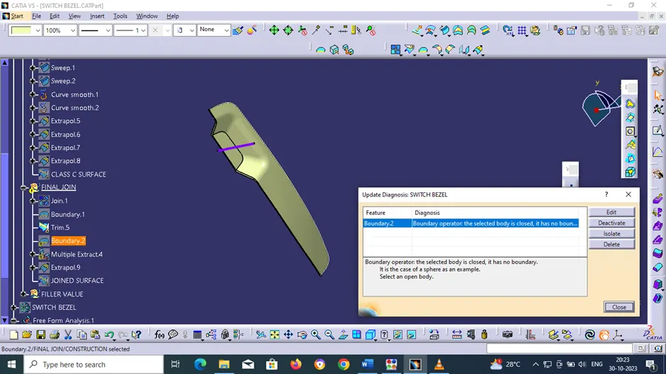
Now check the surface weather it is close or not by boundary command if it get error then it is okay
And if it shows another boundary then it is not okay then by boundary select Trim 5
Boundary 2:
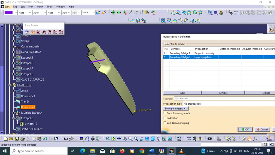
Multiple Extract 4:
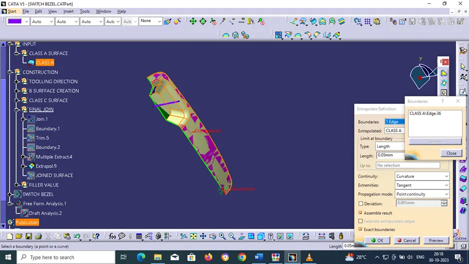
Extrapolate 9:
Joined Surface (Trim 6):
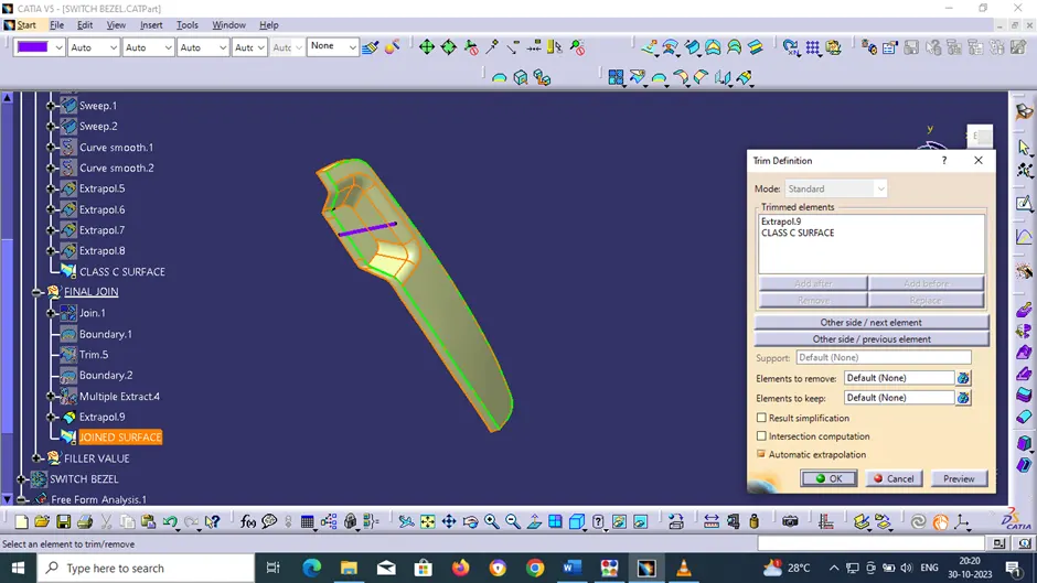
After this procedure boundary 2 will show error so deactivate with all children as shown
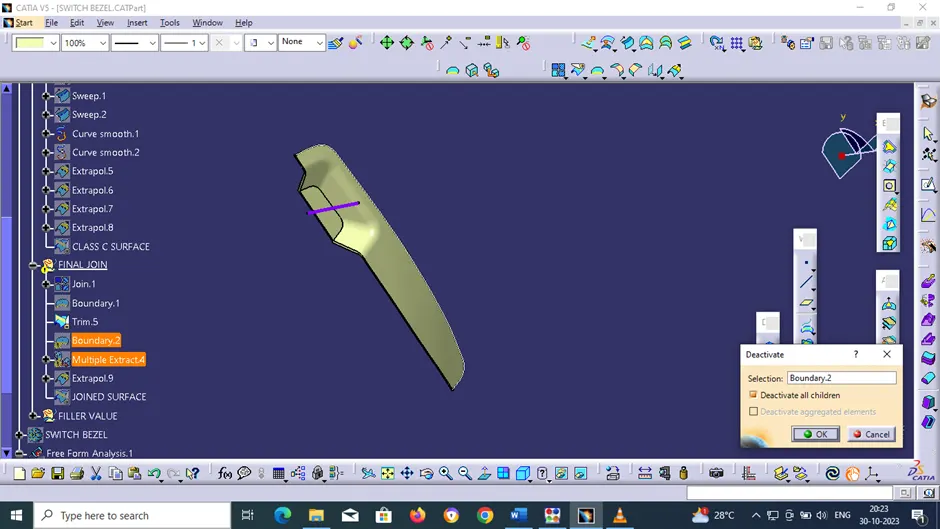
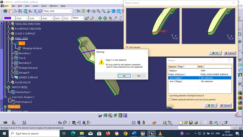
Since Join 1 and Joined Surface (Trim 6) are same instead of using join command we use trim command so we can replace Join 1 to Joined Surface (Trim 6) as shown
Procedure for Close surface creation:
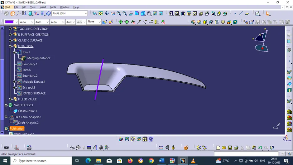
Go to the part design work bench and by using the close surface command create the base bracket solid part body
Close Surface:
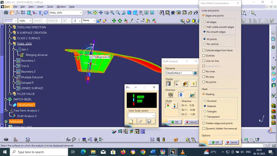
Procedure for Draft Analysis:
- o The part created has to be changed to material mode in display frame
- o Then by enabling compass definition the axis system is pan along the direction of the part and aligned in line with the tooling direction
- o Lock Direction is applied that fixes the compass and then the mode dialog box is formed by snapping at any point on the part
- o The Colour Codes are classified and Draft Angle are applied
- o Then the Running point analysis is used to hover around the part to analyse the permissible draft angles and the analysis is saved
Draft Analysis:
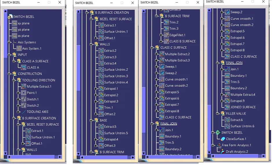
Design Tree Structure:
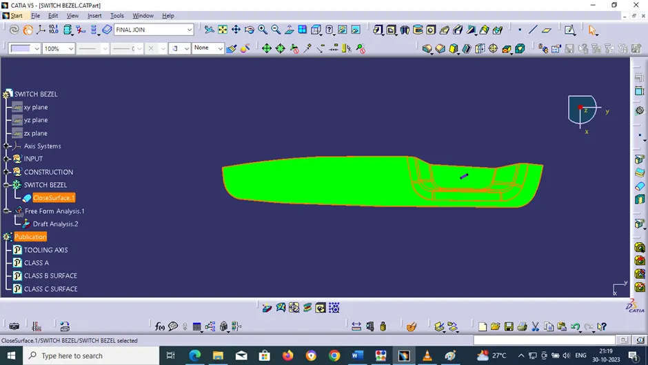
Part mode in various orientations (Isometric, Front, Side, and Top view):
Isometric View:
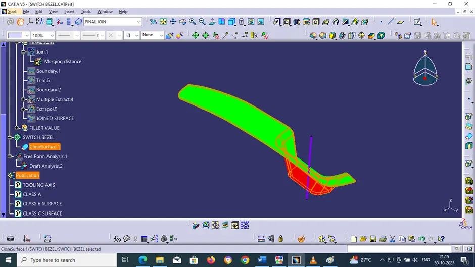
Front View:
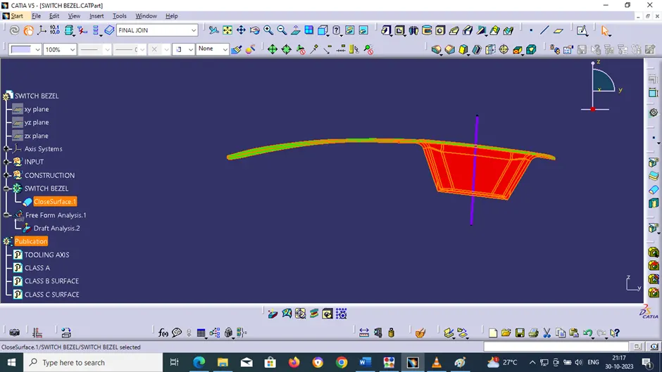
Side View:
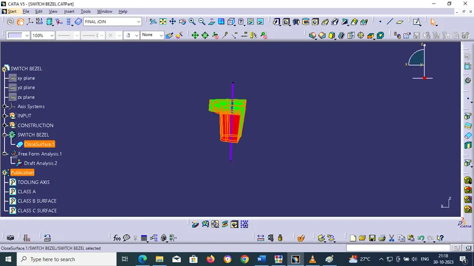
Top View:
Conclusion:
The given A surface is used for creating B and C surface and final joining is done