Project 1
Develop a double-acting actuator model using Simscape Multibody and Simscape components. The mechanical system of the cylinder needs to be built using Simscape Multibody library components / blocks, and the hydraulic system needs to be modelled using Simscape library physical components.
ANSWER
Double acting Cylinder
A double acting cylinder alternates cycles of pressurized fluid to both sides of the piston and creates extend and retract forces to move the piston rod, permitting more control over the movement. Using a control system made up of a 2-, 3-, 4- way position valve would be required to achieve the desired movement for your application.
There are two types of double-acting cylinders:
- Double-acting cylinder with a piston rod on one side.
- Double-acting cylinder with a piston rod on both sides.
Double-Acting Cylinder with a Piston Rod on One Side
Figure 1.4 shows the operation of a double-acting cylinder with a piston rod on one side. To extend the cylinder, the pump flow is sent to the blank-end port as in Fig. 1.4(a). The fluid from the rod-end port returns to the reservoir. To retract the cylinder, the pump flow is sent to the rod-end port and the fluid from the blank-end port returns to the tank as in Fig.1.4(b).
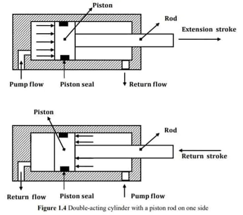
double acting cylinder Diagram
Double-Acting Cylinder with a Piston Rod on Both Sides
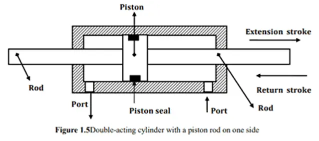
A double-acting cylinder with a piston rod on both sides (Fig.1.5) is a cylinder with a rod extending from both ends. This cylinder can be used in an application where work can be done by both ends of the cylinder, thereby making the cylinder more productive. Double-rod cylinders can withstand higher side loads because they have an extra bearing, one on each rod, to withstand the loading.
Advantages – Single Acting cylinder & Double Acting Cylinder
Single acting hydraulic cylinders are much easier to maintain as their mechanism is comparatively more straightforward. With a single line, the action of the cylinder is entirely based on that one line pressure. Although, they may have an additional spring or something to push or retract the piston rod than often they might depend on the force on end to push it back. It is best to have a simpler mechanism for equipment that needs to be sturdy and dependable.
In case of a double acting cylinder, due to alternates cycles of pressurized fluid to both sides of the piston, the extent and retract forces move the piston rod. This helps to gain maximum control over the movement. A control system made of 2-, 3-, 4- way position valve will be needed to achieve the desired freedom of movement for your application.
Symbol Of Double acting Cylinders:
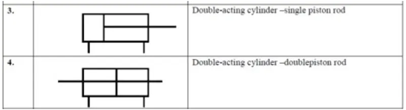
symbol of double acting cylinder
Operation
Hydraulic cylinders get their power from pressurized hydraulic fluid, which is incompressible. Typically oil is used as hydraulic fluid. The hydraulic cylinder consists of a cylinder barrel, in which a piston connected to a piston rod moves back and forth. The barrel is closed on one end by the cylinder bottom (also called the cap) and the other end by the cylinder head (also called the gland) where the piston rod comes out of the cylinder. The piston has sliding rings and seals. The piston divides the inside of the cylinder into two chambers, the bottom chamber (cap end) and the piston rod side chamber (rod end/head-end).
Flanges, trunnions, clevises, and lugs are common cylinder mounting options. The piston rod also has mounting attachments to connect the cylinder to the object or machine component that it is pushing or pulling.
A hydraulic cylinder is the actuator or "motor" side of this system. The "generator" side of the hydraulic system is the hydraulic pump which delivers a fixed or regulated flow of oil to the hydraulic cylinder, to move the piston. There are three types of pump widely used: hydraulic hand pump, hydraulic air pump, and hydraulic electric pump. The piston pushes the oil in the other chamber back to the reservoir. If we assume that the oil enters from the cap end, during extension stroke, and the oil pressure in the rod end/head end is approximately zero, the force F on the piston rod equals the pressure P in the cylinder times the piston area A:
F = P . A
Retraction force difference
For double-acting single-rod cylinders, when the input and output pressures are reversed, there is a force difference between the two sides of the piston due to one side of the piston being covered by the rod attached to it. The cylinder rod reduces the surface area of the piston and reduces the force that can be applied for the retraction stroke.
During the retraction stroke, if the oil is pumped into the head (or gland) at the rod end and the oil from the cap end flows back to the reservoir without pressure, the fluid pressure in the rod end is (Pull Force) / (piston area - piston rod area):
P = Fp/(Ap – Ar)
where P is the fluid pressure, Fp is the pulling force, Ap is the piston face area and Ar is the rod cross-section area.
For double-acting, double-rod cylinders, when the piston surface area is equally covered by a rod of equal size on both sides of the head, there is no force difference. Such cylinders typically have their cylinder body affixed to a stationary mount.
Applications
Hydraulic cylinders are used in earth moving equipment such as excavators, back hoes and tractors to lift or lower the boom, arm, or bucket. These cylinders are also used in hydraulic bending machine, metal sheet shearing machines,particle board or plywood making hot press.
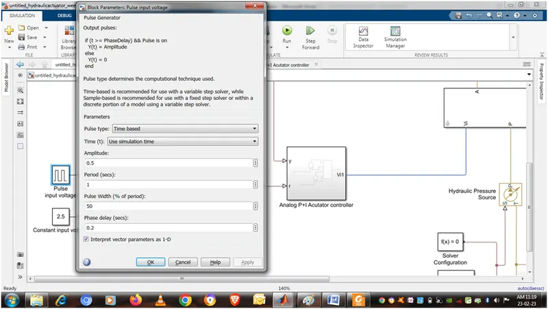
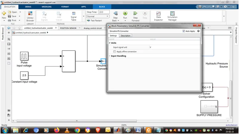
PULSE INPUT VOLTAGE
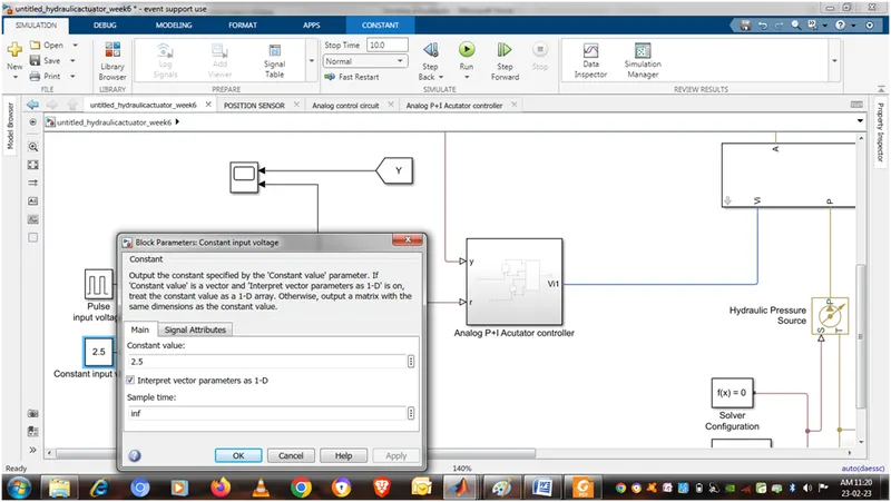
CONSTANT INPUT VOLTAGE
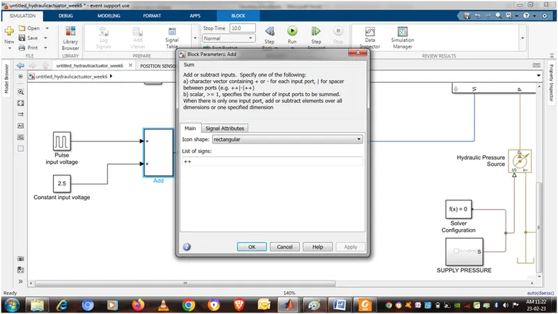
SUM
SIMULINK PS CONVERTER
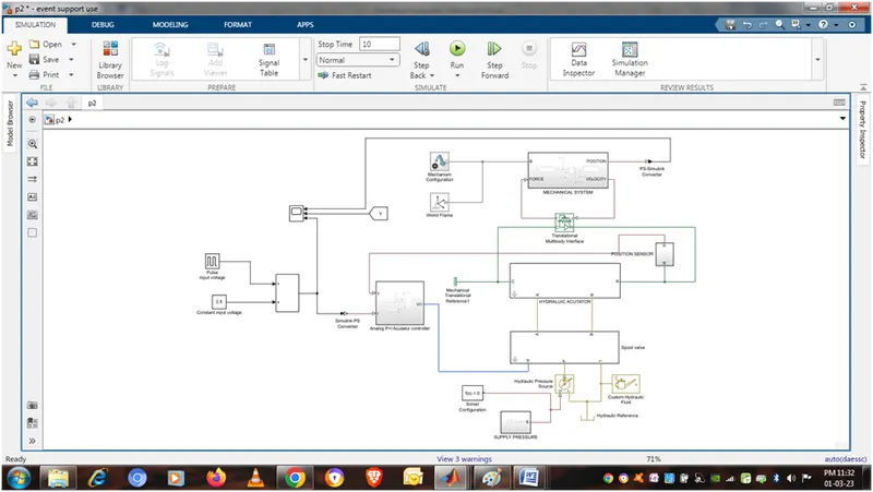
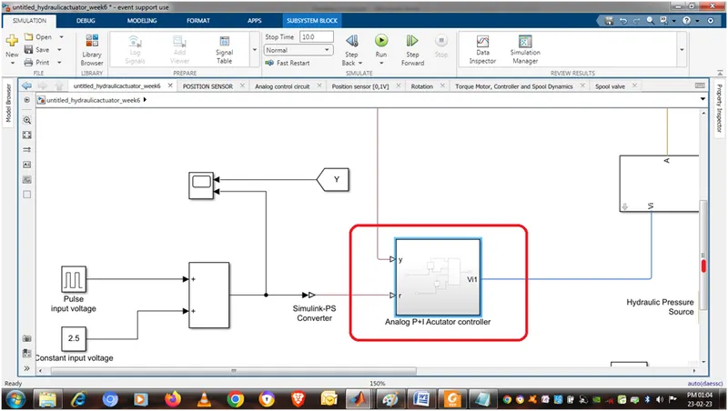
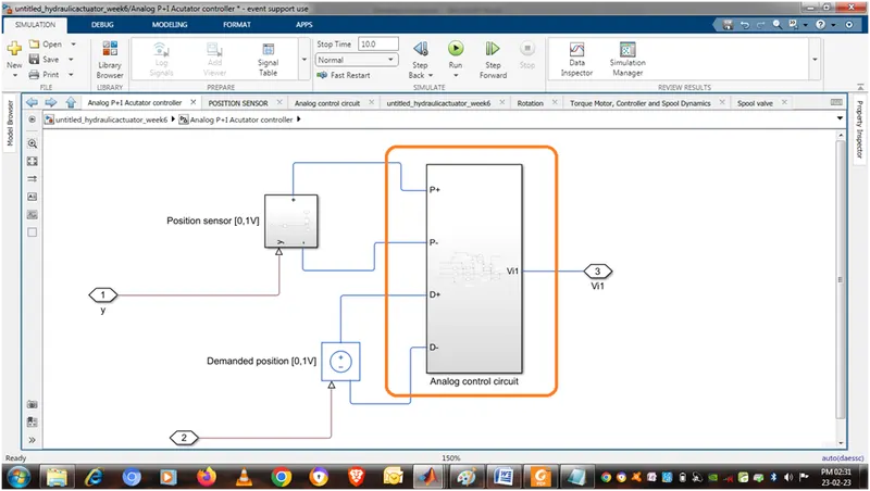
ANALOG P+I ACTUTATOR CONTROL
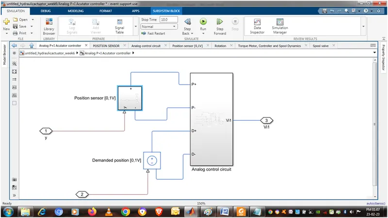
INSIDE ANALOG P+I ACTUTATOR CONTROL
CONTAIN POSITION SENSOR DEMANDING POSITION AND ANALOG CONTROL CIRCUIT
POSITION SENSOR
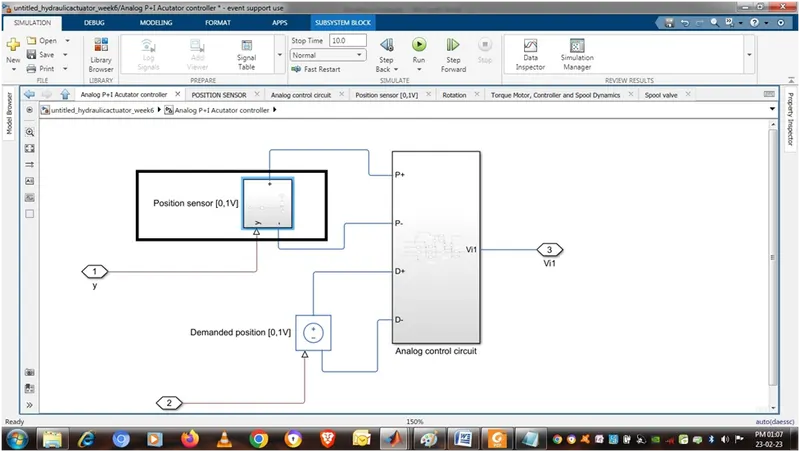
INSIDE POSITION SENSOR
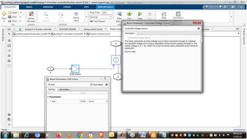
ANALOG CONTROL CIRCUIT
INSIDE ANALOG CONTROL CIRCUIT
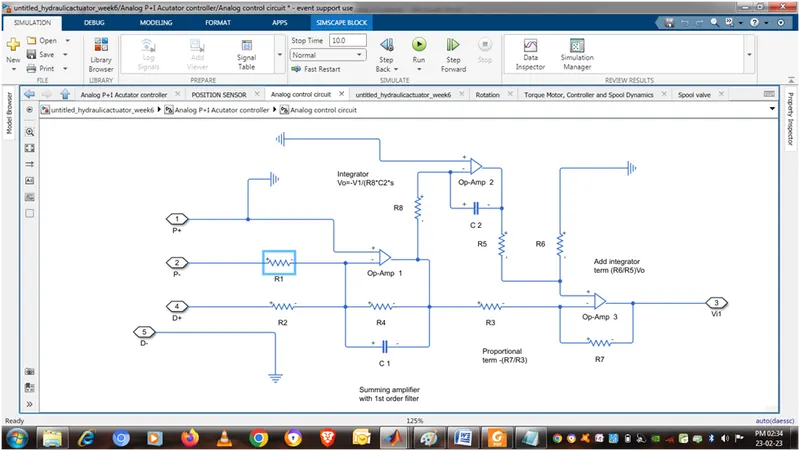
PUT THE VALUE OF RESISTOR
R1=10 Kilo-ohm=10e3 ohm, R2=10 Kilo-ohm=10e3 ohm , R3=10 Kilo-ohm=10e3 ohm , R4=5.7 Kilo-ohm=5.7e3 ohm, R5=10 Kilo-ohm=10e3 ohm, R6=10 Kilo-ohm=10e3 ohm , R7=20 Kilo-ohm=20e3 ohm , R8=10 Kilo-ohm=10e3 ohm
PUT THE VAUE OF CAPACITOR
C1 PARAMETER AS
CAPACITANCE=0.15 microfarad=0.15e-06 F , SERIES RESISTANCE= 1micro-ohm = 1e-06 ohm ,
PARALLEL CONDUCTANCE = 0 per ohm = 0/ohm
C2 PARAMETER AS
CAPACITANCE=100 microfarad= 100e-06 F , SERIES RESISTANCE= 1micro-ohm = 1e-06 ohm ,
PARALLEL CONDUCTANCE = 0 per ohm = 0/ohm
CONNECT OP AMP ,RESISTOR, CAPACITOR AS SHOWN IN ABOVE FIGURE
INSIDE SPOOL VALVE
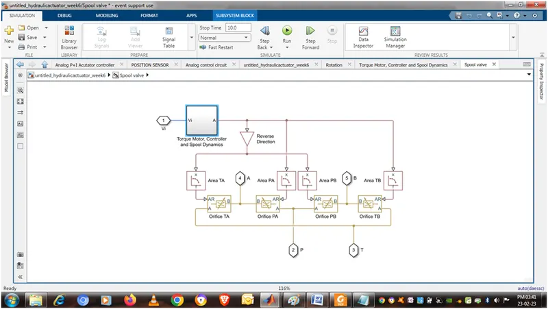
TORQUE MOTOR, CONTROLLER AND SPOOL DYNAMICS IS CONNECTED CONNECTED TO PS GAIN , PS LOOKUP TABLE (1D) , VARIABLE AREA HYDRAULIC ORIFICE
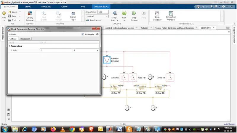
PS GAIN
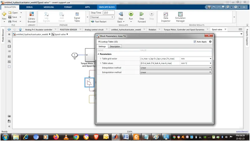
PS LOOKUP TABLE (1D)
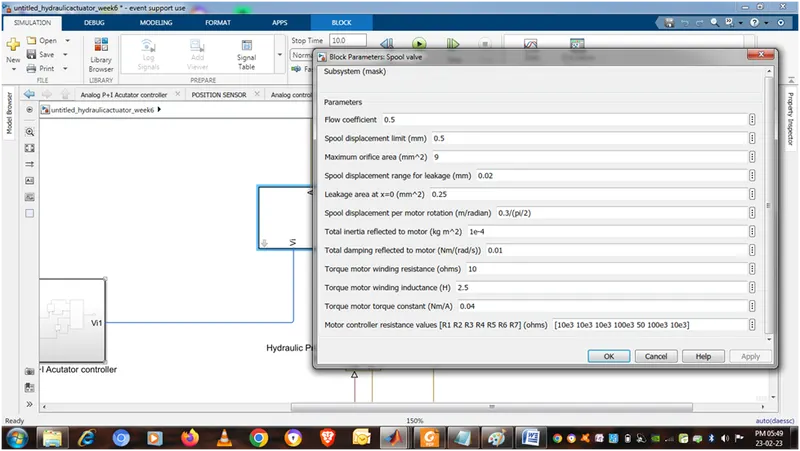
Spool displacement limit=x_max=0.5 mm
Spool displacement range of leakage= x_lap=0.02 mm
Leakage area at with x as zero=A_leak =0.25 mm^2
2*Leakage area at with x as zero 2*A_leak= 2*0.25=0.5 mm^2
Maximum orifice area=A_max=9 mm^2
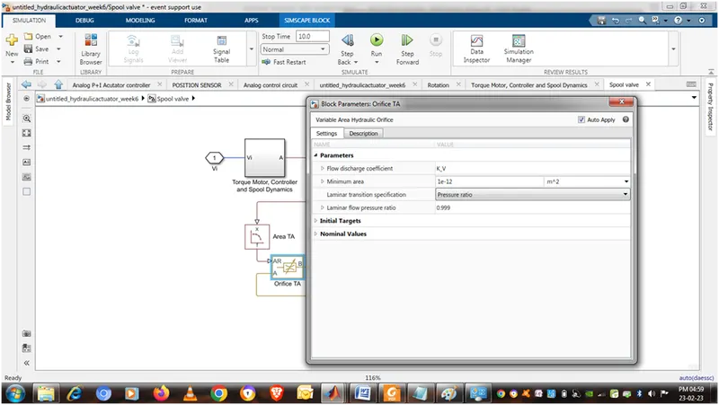
VARIABLE AREA HYDRAULIC ORIFICE
Flow discharge coefficient= K_V=0.5
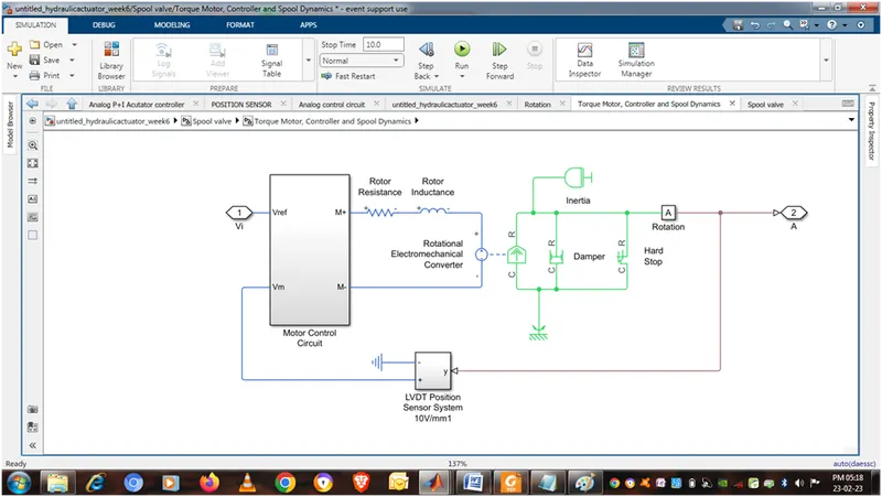
INSIDE TORQUE MOTOR, CONTROLLER AND SPOOL DYNAMICS
MOTOR CONTROL CIRCUIT IS CONNECTED ROTOR RESISTOR,ROTOR INDUCTANCE, ROTATIONAL ELECTROMECHANICAL CONVERTER , ROTATIONAL DAMPER ROTATIONAL HARD STOP , INERTIA , ROTATIONAL REFERENCE,ROTATION, LVDT POSITION SENSOR
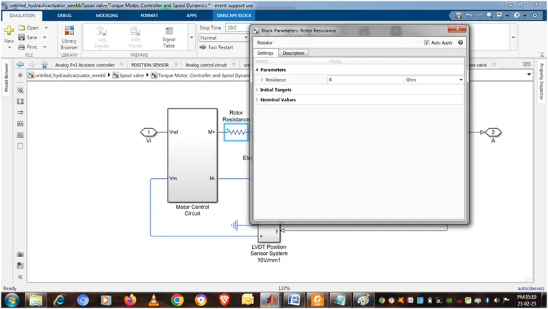
ROTOR RESISTANCE
TORQUE MOTOR WINDING RESISATANCE=R=10 ohm
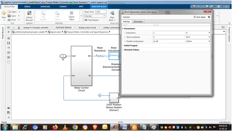
ROTOR INDUCTANCE
TORQUE MOTOR WINDING INDUCTANCE = L=2.5 H
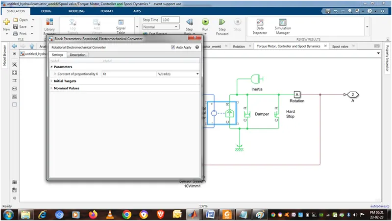
ROTATIONAL ELECTROMECHANICAL CONVERTER
TORQUE MOTOR CONSTANT =Kt=0.04 V/(rad/s)
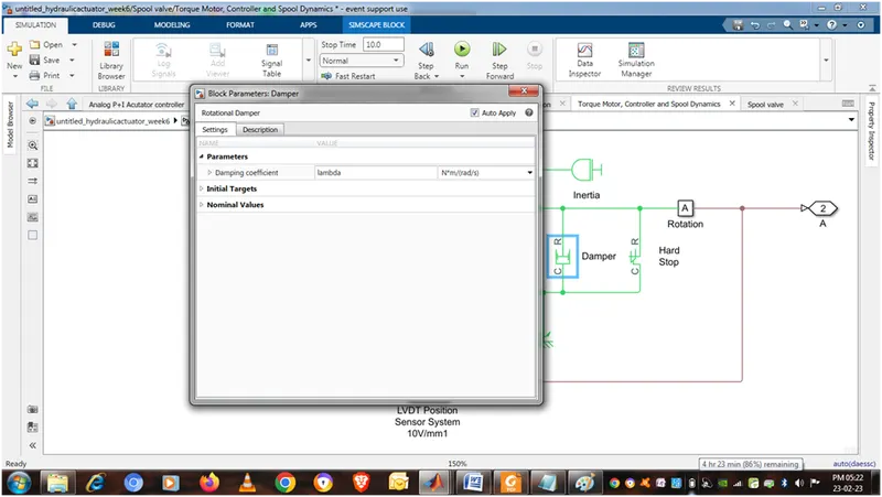
ROTATIONAL DAMPER
TOTAL DAMPING REFLECTED TO MOTOR=lambda=0.01 Nm/(rad/s)
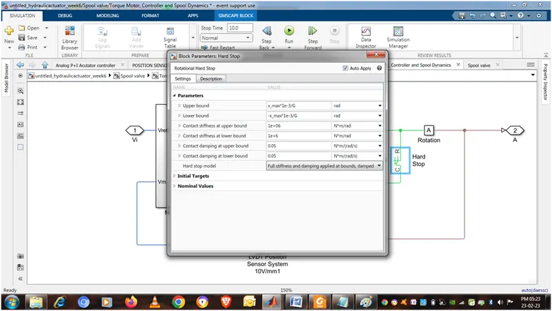
ROTATIONAL HARD STOP
x_max=0.5
spool displacement per motor rotation =G=0.3/(pi/2) m/radian
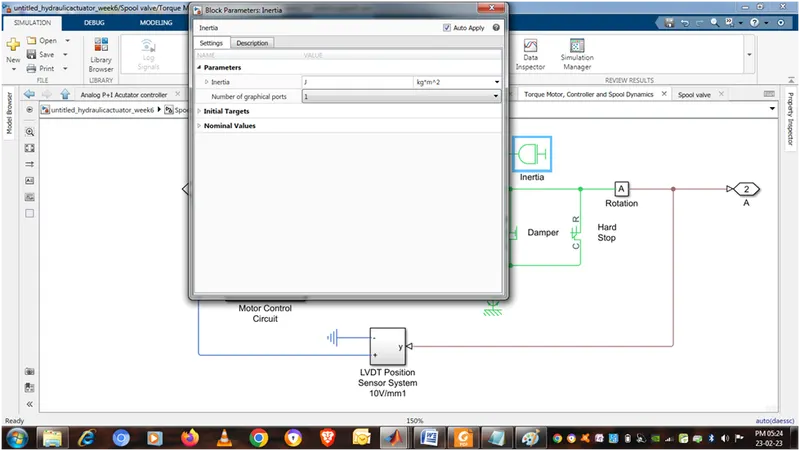
INERTIA
Total inertia reflected to motor=J=1e-4 kgm^2
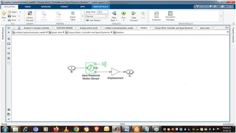
INSIDE ROTATIONAL
IDEAL ROTATIONAL MOTION SENSOR , PS GAIN AS DISPLACEMENT AND ROTATIONAL REFERENCE IS CONNECTED AS SHOWN
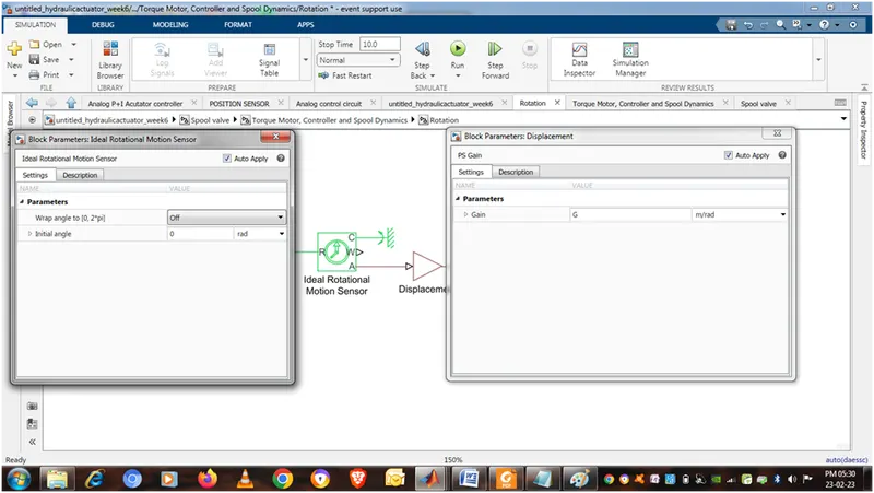
PARAMETER OF IDEAL ROTATIONAL MOTION SENSOR , PS GAIN AS DISPLACEMENT
G=0.3/(pi/2) m/radian
INSIDE LVDT POSITION SENSOR SYSTEM
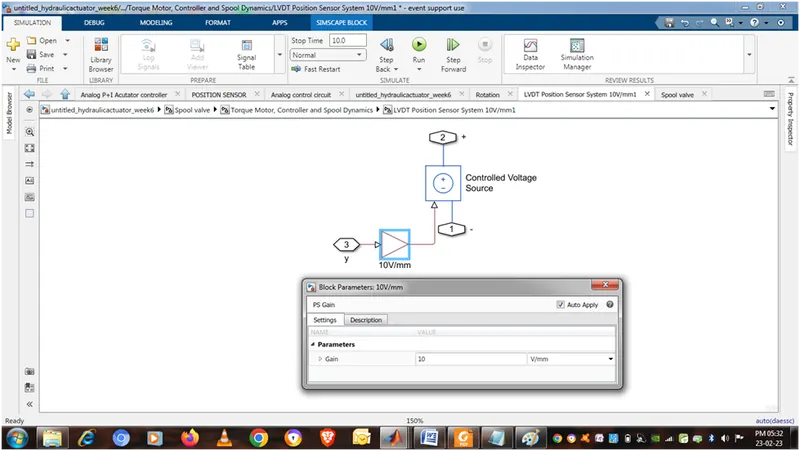
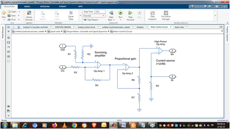
INSIDE MOTOR CONTROL CIRCUIT
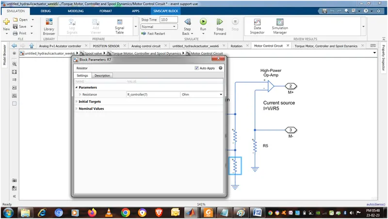
RESISTOR FROM 1 TO 7 AND OP Amp are connected as shown
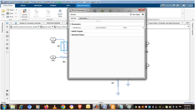
R1=R_contreller(1)=10e3 ohm
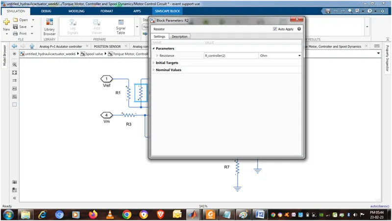
R2=R_contreller(2)=10e3 ohm
R3=R_contreller(3)=10e3 ohm
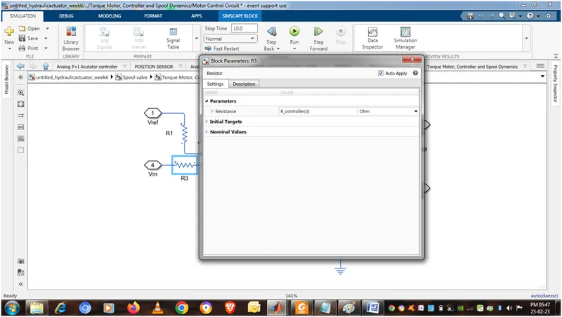
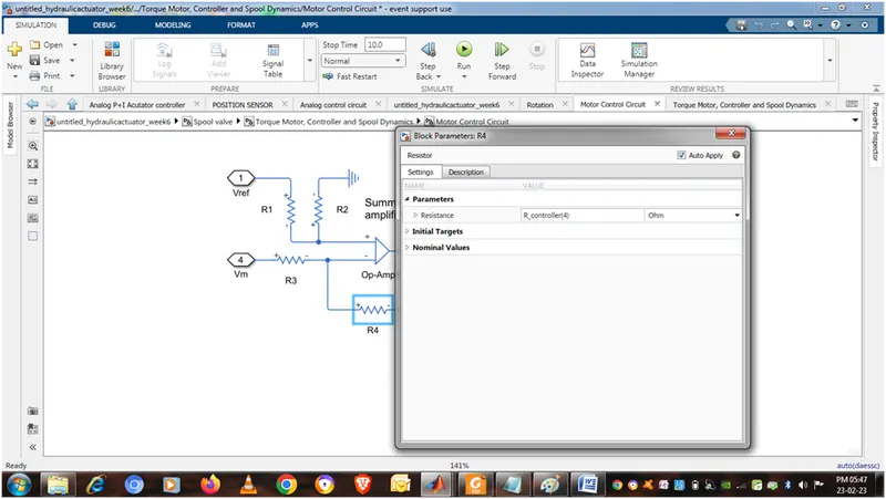
R4=R_contreller(4)=100e3 ohm
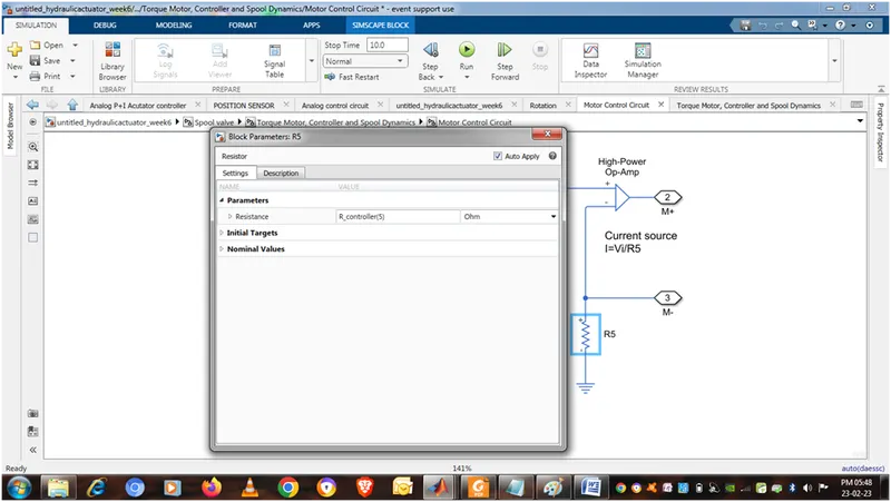
R5=R_contreller(5)=50e3 ohm
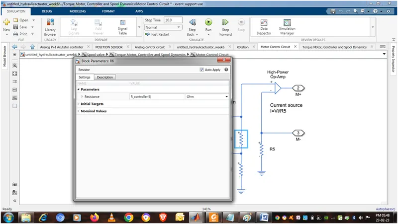
R6=R_contreller(6)=100e3 ohm
R7=R_contreller(7)=10e3 ohm
Spool valve parameter
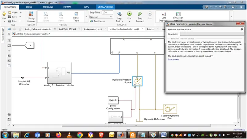
Spool valve connected to
Vi with Analog P+I Acutator controller
P with Hydraulic pressure source
T with Hydraulic reference & custom hydraulic fluid
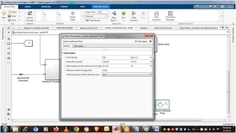
CUSTOM HYDRAULIC FLUID PARAMETER
Solver configuration and supply pressure connect hydraulic pressure source
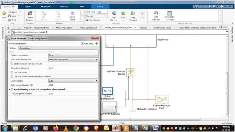
Supply pressure
Constant value =200
Simulink ps convertor with input signal value bar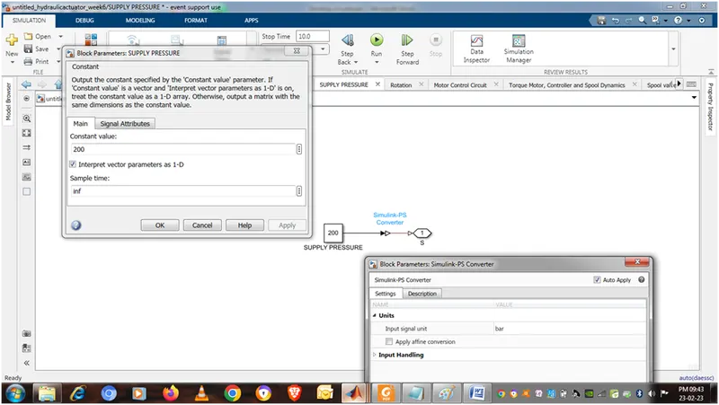
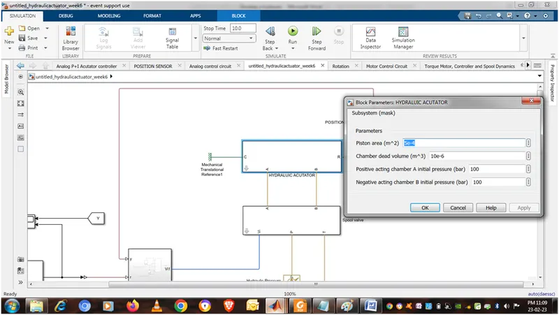
HYDRAULIC ACTUATOR A & B PORT CONNECT WITH A & B PORT OF SPOOL VALVE
C PORT CONNECT WITH MECHANICAL TRANSALATION REFERENCE
R PORT CONNECT WITH MASS, POSITION SENSOR, TRANSLATION HARD STOP, TRANSLATION DAMPER, TRANSLATION SPRING
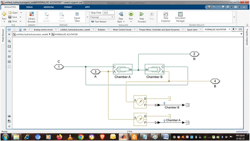
INSIDE HYDRAULIC ACTUATOR
Here in chamber A & B both R port are inter connected
Both c port are interconnected
Port A of both chamber are individually connected with A port of hydraulic pressure sensor
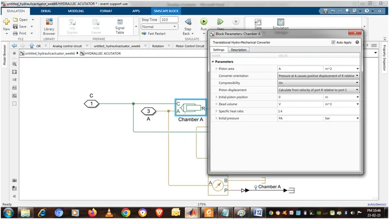
TRANSLATIONAL HYDROMECHANICAL CONVERTER OF CHAMBER A
PISTON AREA = A=5e-4 m^2
DEAD VOLUME = V= 10e-6 m^3
INITIAL PISTON POSITION = 0 m
INITIAL PRESSURE = PA = 100 bar (positive acting)
TRANSLATIONAL HYDROMECHANICAL CONVERTER OF CHAMBER B
PISTON AREA = A=5e-4 m^2
DEAD VOLUME = V= 10e-6 m^3
INITIAL PISTON POSITION = 50 mm
INITIAL PRESSURE = PA = 100 bar (negative acting)
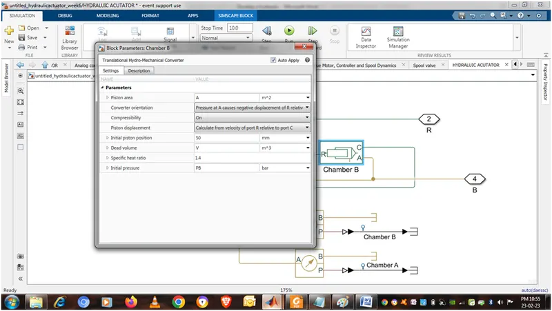
HYDRAULIC PRESSURE SENSOR
A PORT CONNECTED WITH A PORT OF CHAMBER
B PORT CONNECT WITH HYDRAULIC REFERENCE
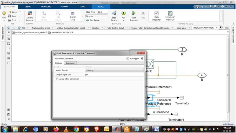
P PORT CONNECT WITH TERMINATOR THROUGH SIMULINK PS CONVERTOR
SIMULINK PS CONVERTOR VALUE AS
NOW THE SUBSYSTEM HYDRAULIC ACTUTATOR PARAMETER IS
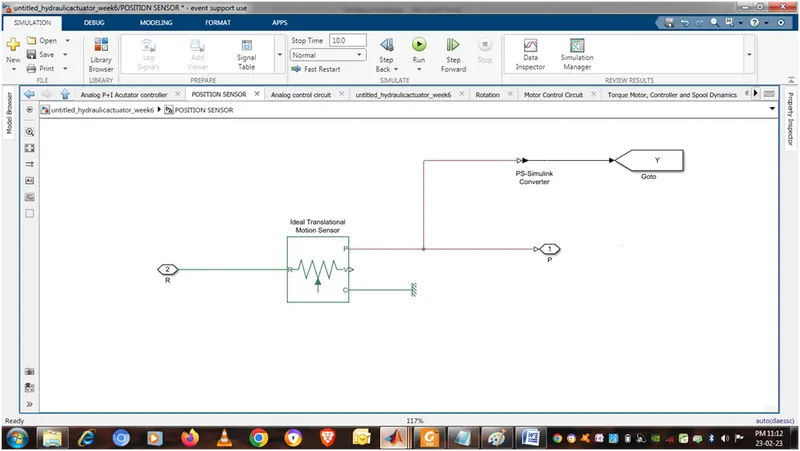
POSITION SENSOR
inside position sensor
ideal translational motion sensor
r port connect with r port of hydraulic actutor
p port connect with goto port trough ps simulink converter
p port also connect with y port of analog p+i actuator controller
v port is terminated
c port is connect with mechanical translational reference
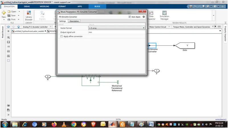
PS SIMULINK CONVERTER VALUE AS
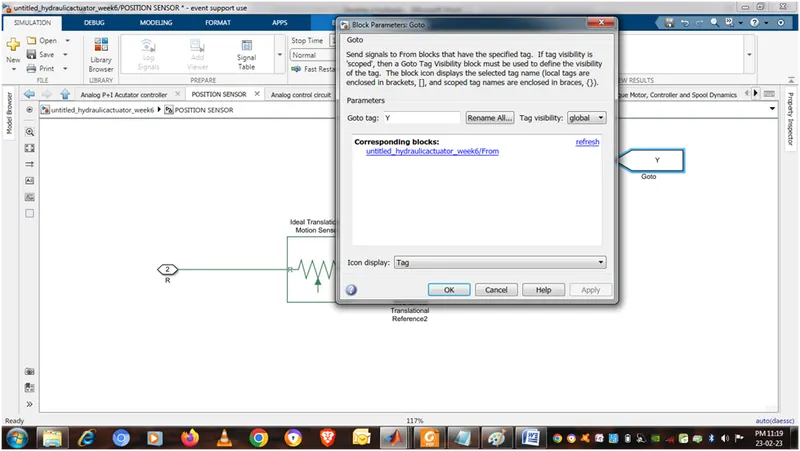
GOTO VALUE AS
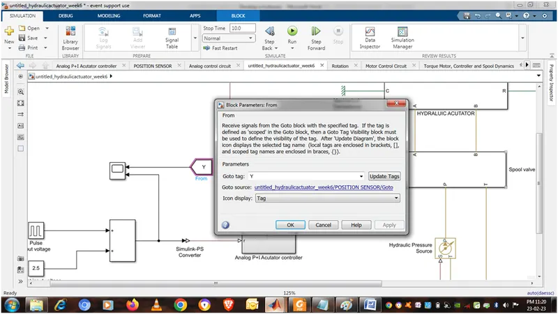
FROM CONNECT WITH SCOPE
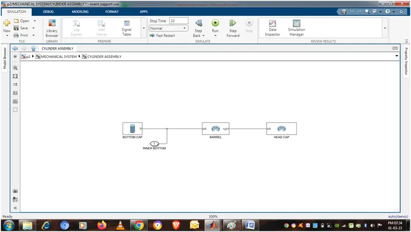
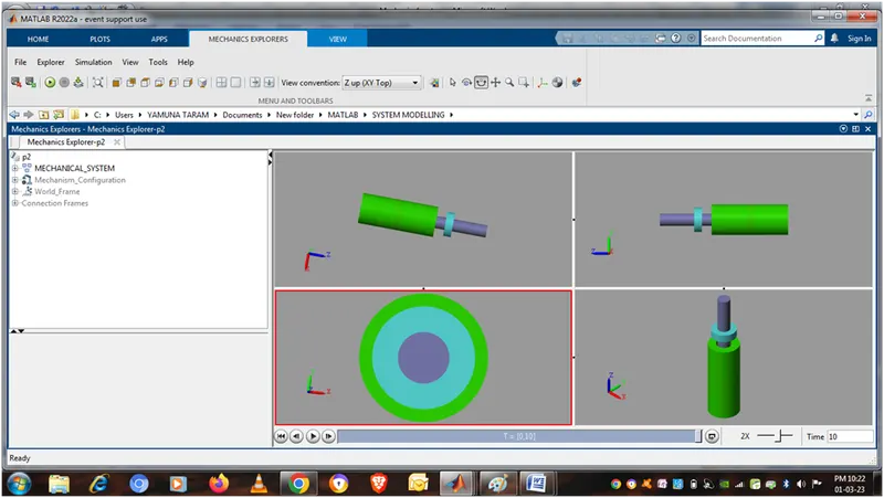
Mechanical system
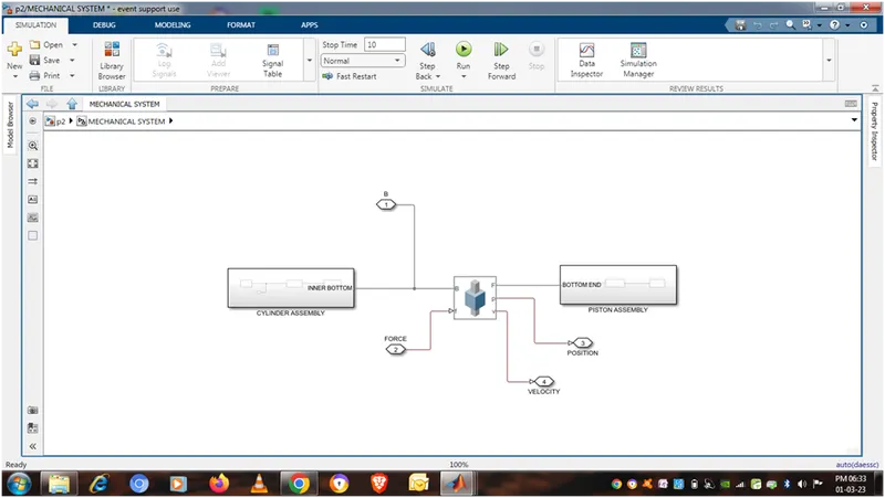
Cylinder assembly
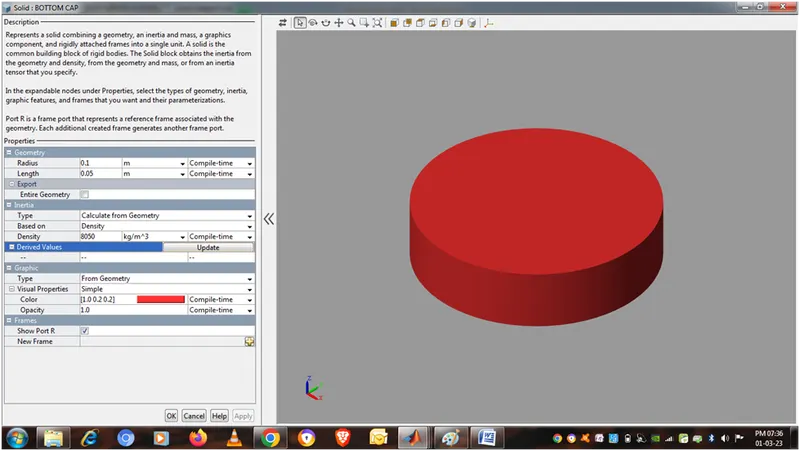
Solid cylinder as bottom cap
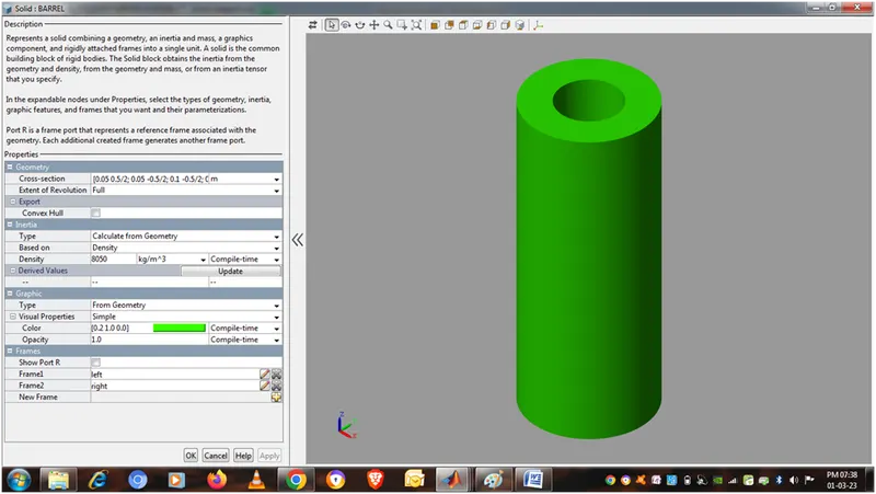
Revolved solid as barrel
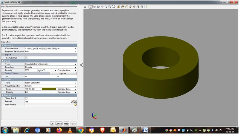
Revolved solid as head cap
Prismatic joint
Represents a prismatic joint between two frames. This joint has one translational degree of freedom represented by one prismatic primitive. The joint constrains the follower origin to translate along the base z-axis, while the base and follower axes remain aligned.
In the expandable nodes under Properties, specify the state, actuation method, sensing capabilities, and internal mechanics of the primitives of this joint. After you apply these settings, the block displays the corresponding physical signal ports.
Ports B and F are frame ports that represent the base and follower frames, respectively. The joint direction is defined by motion of the follower frame relative to the base frame.
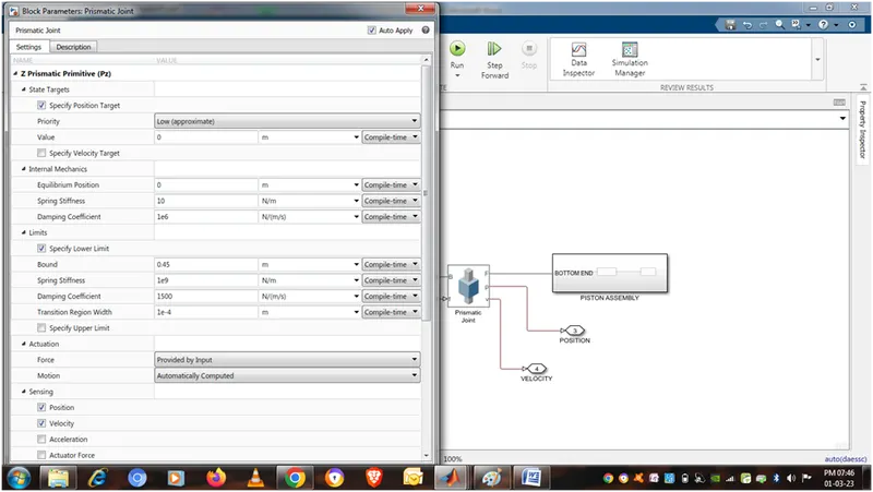
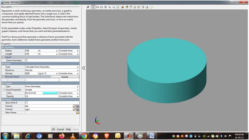
Piston assembly
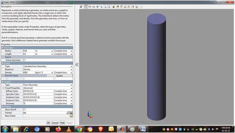
Cylinder solid as piston
Cylinder solid as rod
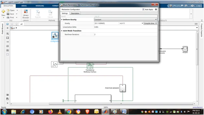
Mechanical configuration
Sets mechanical and simulation parameters that apply to an entire machine, the target machine to which the block is connected. In the Properties section below, you can specify uniform gravity for the entire mechanism and also set the linearization delta. The linearization delta specifies the perturbation value that is used to compute numerical partial derivatives for linearization.
Port C is frame node that you connect to the target machine by a connection line at any frame node of the machine.
Word frame
Provides access to the world or ground frame, a unique motionless, orthogonal, right-handed coordinate frame predefined in any mechanical model. World frame is the ground of all frame networks in a mechanical model.
A model can have multiple World Frame blocks, but all represent the same frame.
Port W is a frame port identified with the world frame. Any frame port directly connected to W is also identified with the world frame.
Translational Multibody Interface
This block is an interface between a Simscape Multibody joint and a Simscape mechanical translational network. Ports R and C are mechanical translational conserving ports that connect to the two nodes in the mechanical translational network which share the same force and relative velocity as a primitive in the Multibody joint. Ports v and f are physical signal ports that connect to the Multibody joint. Input port v accepts the relative velocity sensing output from the joint primitive. Output port f provides the force actuation input to the joint primitive.
PS-Simulink Converter
Converts the input Physical Signal to a Simulink output signal.
Format of Simulink output signal matches the format of Physical Signal. 'Vector format' provides an option for outputting vector Physical Signals as Simulink 1-D arrays.
The unit expression in 'Output signal unit' parameter must match or be commensurate with the unit of the Physical Signal and determines the conversion from the Physical Signal to the Simulink output signal.
Mechanics explorer
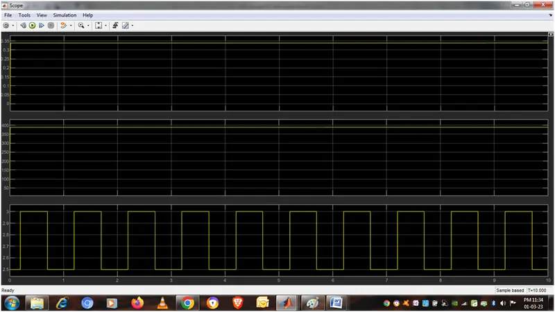
Scope result as