Week 9 - Challenge 2 - Switch Bezel Design
AIM:
To Create the Switch Bezel Plastic component through the given Class-A surface. To begin with, the tooling axis for the given Class-A Surface should be created meeting the requirements of the draft angle and at the end perform the Draft analysis on the model.
Introduction:
CLASS-A SURFACE: The class-A surface is used in the automotive design industry. it describes the final production surface data for the aesthetic parts.
CLASS-B SURFACE: the class-B surface is the second surface that has a certain thickness from the class-A surface. this surface contains engineering aspects of a model. These must be smooth and "error-free" as well but are not held to the standards that class A surfaces are.
CLASS-C SURFACE: The Class C finish allows more imperfections than Class A or B. Class C is often specified for interior surfaces not readily visible, surfaces that will be covered by another part when assembled, or surfaces.
Design Procedure:
1. Insert the class A surface of the switch bezel in CATIA software.
2. Determining the tooling axis for the switch bezel
3. Creation of class B surface.
4. Creation of class c surface.
5. Join the switch bezel's class A, class B, and class c surfaces and ensure all the surfaces are closed surfaces.
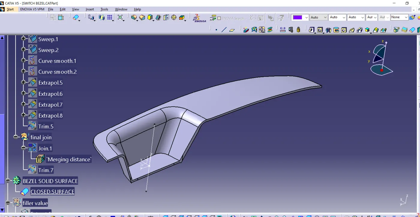
6. Use the Close Surface feature to make a solid body from the surface.
7. finally, Perform the Draft analysis on the switch bezel final plastic component.
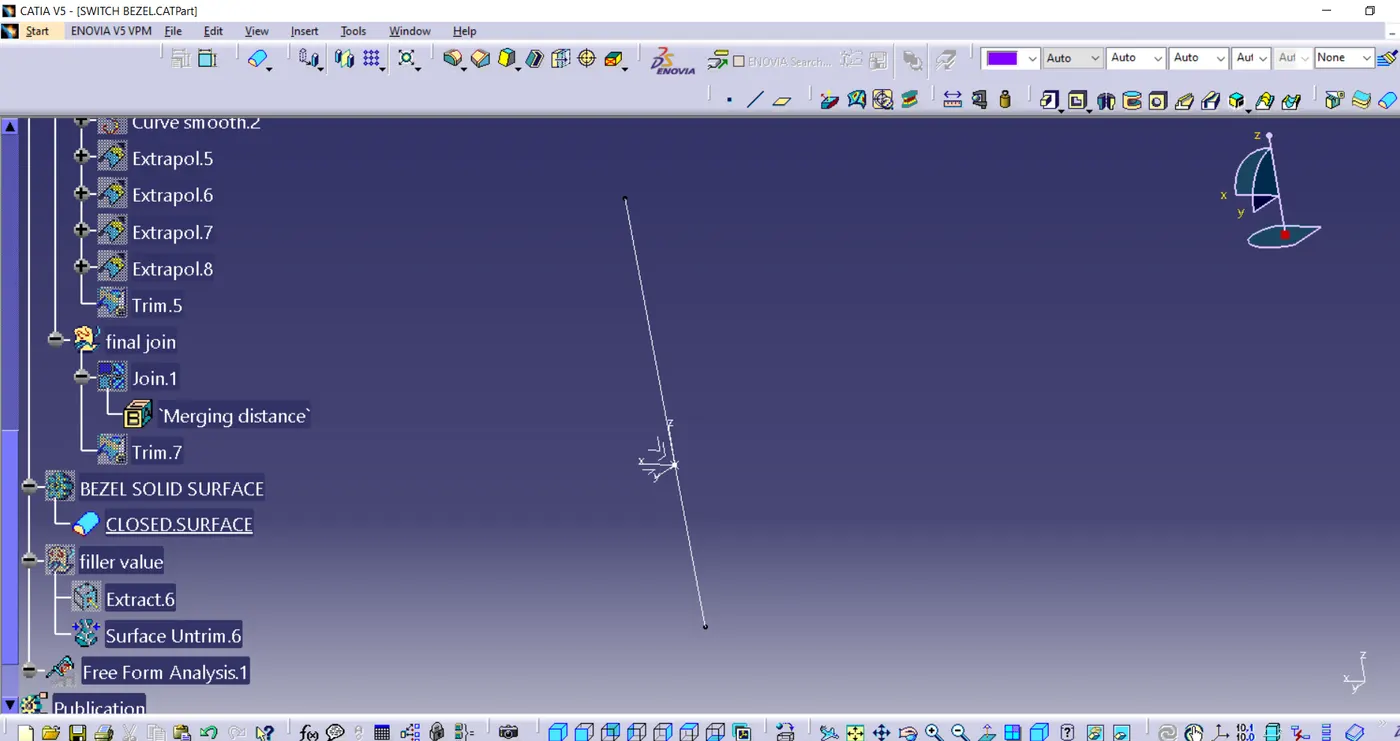
Creation of tooling axis:
1. The ejection from the mold after manufacturing the interior trim must have the nominal 3-degree draft angle.
2. Hence the tooling directions created by considering the above factor and bisecting method is used.
3. The base surface of the class-A was extracted to create a reference point on the surface using the point, create a line in the z-direction and an axis system was inserted to the point
4. Then using projection intersection along the yz plane is created and the two inclined lines were drawn inside the positioned sketch.
then bisecting lines with the two inclined lines were created.
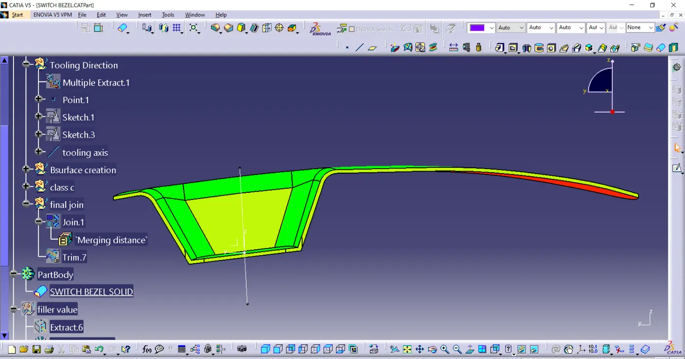
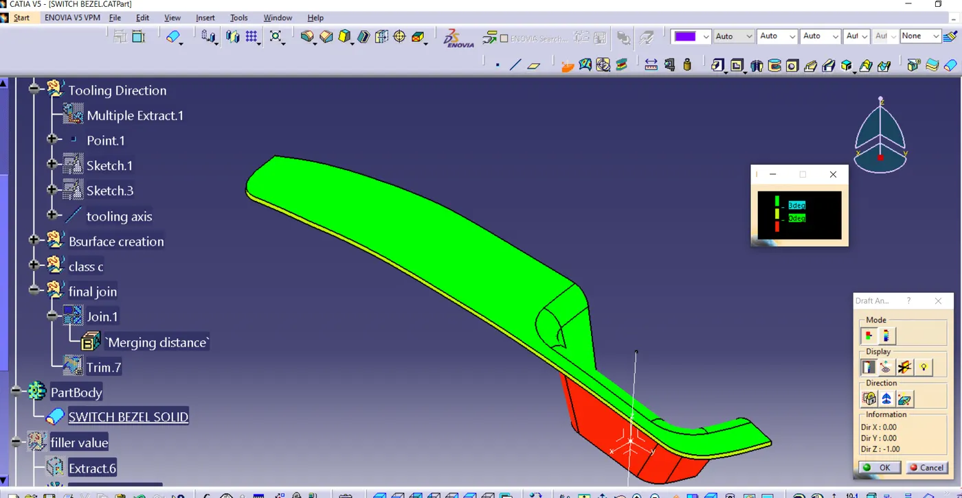
DRAFT ANALYSIS ON CLASS-A SURFACE:
- 1. Go to insert> analysis> feature draft analysis.
- 2. Align the tooling axis with the compass.
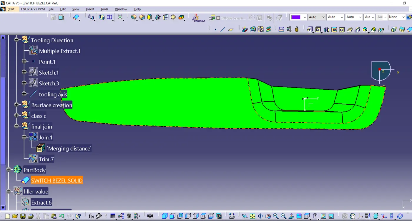
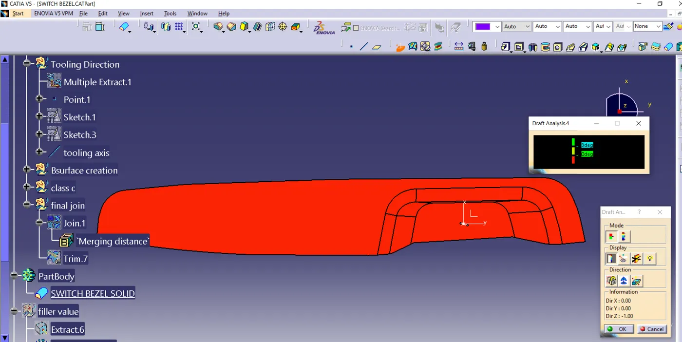
- 3. Click on the surface and see that the surface is within the permissible limit of the draft values.
- 4. The surface should be green and in the column nominal value 3deg given as input. hence the draft analysis on the class-A surface is successfully performed.
Screenshots of Draft analysis are as follows:
Front view:
Top View:
Back View:
Isometric view:
Final View solid View of Bezel switch panel with 2.5mm thickness:
Please find attached part file.