Week 9 - Challenge 2 - Switch Bezel Design
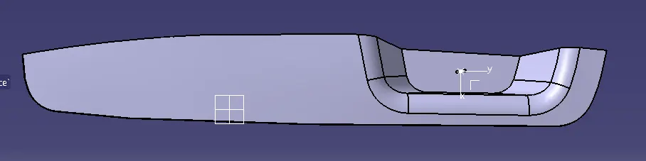
AIM: To make a switch bazel from the provided class-A surface.
Types of Surfaces in design:
CLASS-A SURFACE: a surface made by the designer which is given as an input to the plastic modeler to work on. It is aesthetic surface and the outer most surface.
CLASS-B SURFACE: a surface below a certain thickness from the class-A surface is class-B surface. This is the surface that contains engineering aspects of a model.
CLASS-C SURFACE: a surface that joins class-A and class-B surfaces is class-C surface.
Below given tools were used to design base bracket:
FOR TOOLING AXIS:
First ensure the class-A surface is properly joined and has no discontinuity on it.
Use boundary command or join command to check continuity
This component requires two axis to define tooling axis.
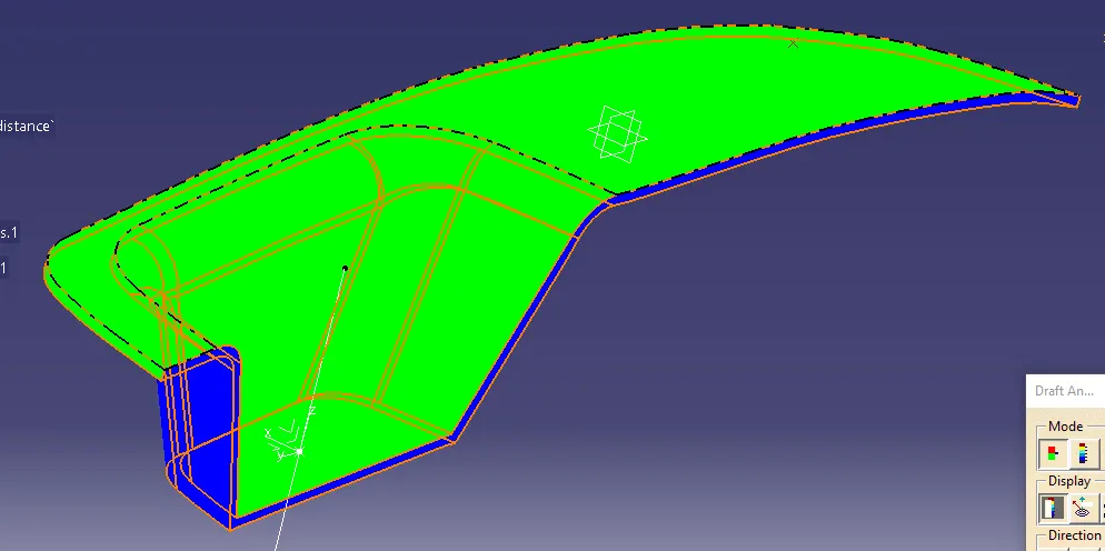
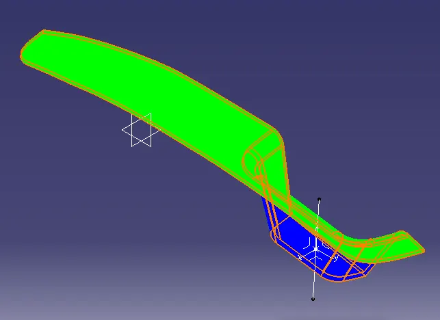
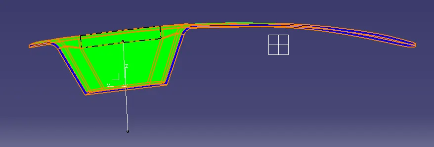
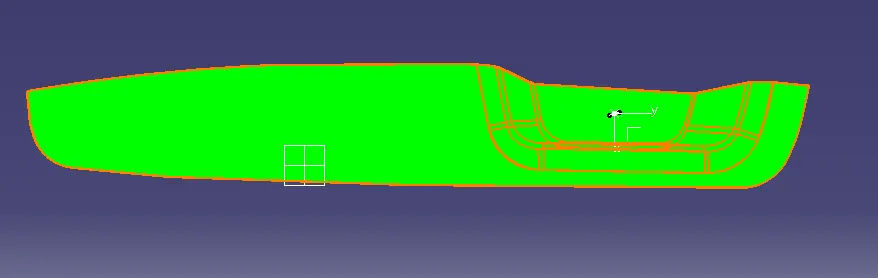
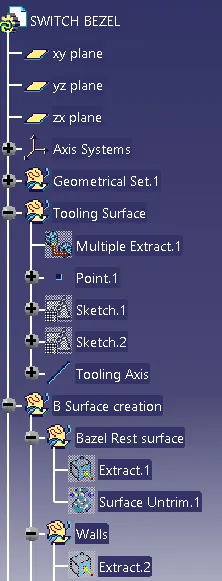
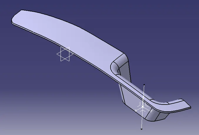
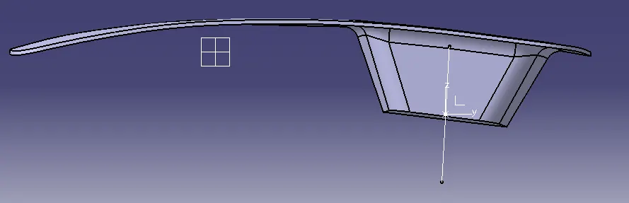
Axis system is inserted at the center of switch bazel base shown in images.
At this system's origine one origin point is created to use as reference point through which tooling axis will pass.
As the first axis is created in YZ plane.
Another axis is created in XZ plane.
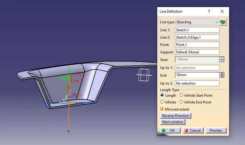
After that tooling axis is created by using these two lines mentioned earlier by bisecting method.
Now, create line as shown in image from 3D projecting option.
Select on line option, choose bisecting method to create line.
Now tooling axis is created.
Required images are given below: