Week 9 - Challenge 2 - Switch Bezel Design
AIM:-
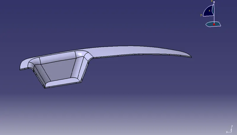
To Create the Switch Bezel Plastic component through the given Class-A surface. To begin with, the tooling axis for the given Class-A Surface should be created meeting the requirements of the draft angle and at the end perform the Draft analysis on the model. The thickness of the component to be 2.5 mm.
DESCRIPTION:-
- Geometrical sets should have a proper name based on the sketches present inside of it.
- All the sketches should be created under the Geometrical set.
- Used the Close Surface feature to make a solid body from the surface.
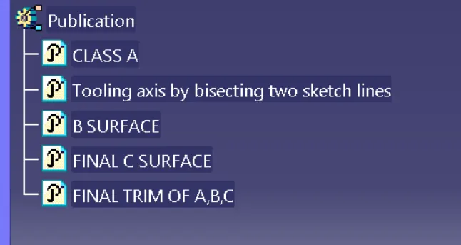
- Publications: Using the publication option and published the below
- Tooling Axis
- Class A, B, and C surface.
The tooling axis creation:-
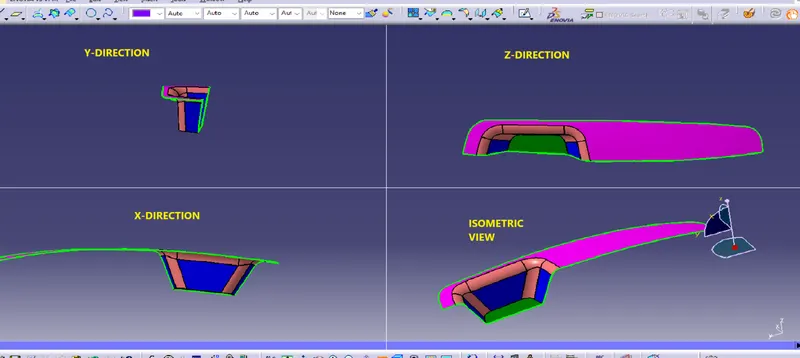
From the above image the z direction will be the best approach for the tooling axis. so we will going to create tooling axis for the surfaces which is simple and having no fillets. The surfaces were marked as blue & green color, pink is a large & flat surface so it will be cleared along the tooling axis of the blue surface, along y direction the tooling axis is created by making a point in centre of the green surface (which is extracted), intersecting the the class A along y direction and creating sketches on the intersected surface (lines over the intersecting surface) & by using bisecting lines created a mean line between the two lines over the surface intersection which will be our tooling axis for the blue surfaces along y direction. For the blue surface along x direction which is little inclined inside which is not visible from z direction for that we are going to create a tooling axis by using the intersection of surface along x direction and creating a sketch(line) over the intersected surface and making another line along the z direction over the point and make them both constraint with 3deg angle which is the nominal value for draft angle. After creating two tooling axis for the two surfaces with the help of bisecting lines here we have created a tooling axis by bisecting the two tooling axis now we had a tooling axis which will clear all the class A surfaces.
Draft analysis report:-
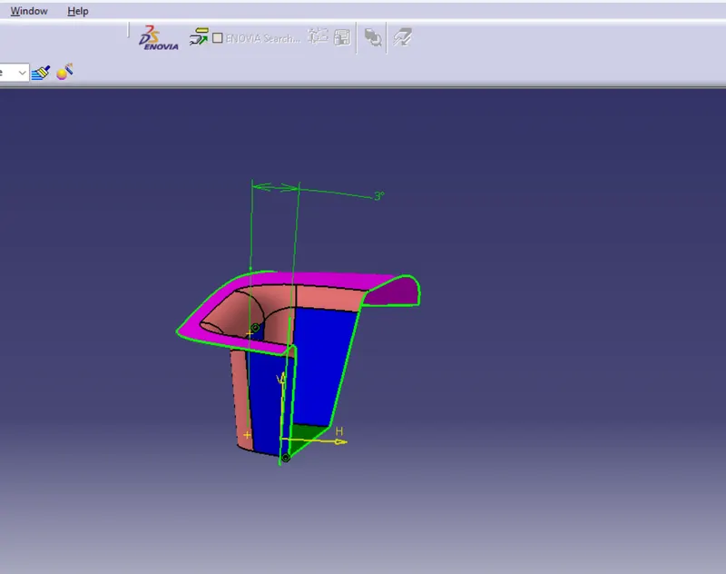
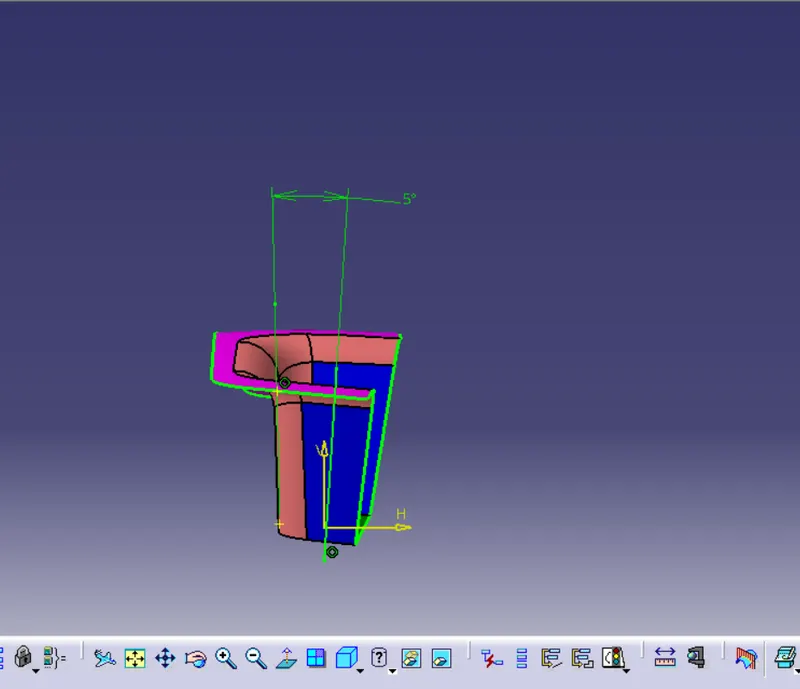
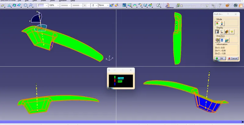
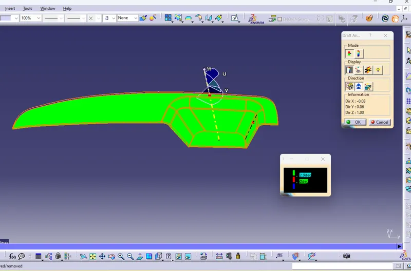
After creating the tooling axis draft analysis is done over the class A surface with the given 3deg angle for the surface in x direction it is not clearing the draft angle 3deg so here we've changed the angle of the sketch 2 tooling axis to 5deg for the surface which is in x direction then again perfomed draft analysis now its showing positive draft of 3 deg all over the given class A surface from the final tooling axis.
Screenshots of the Draft analysis report for both the given Class-A surface and the final plastic component:-
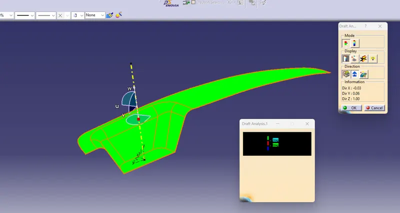
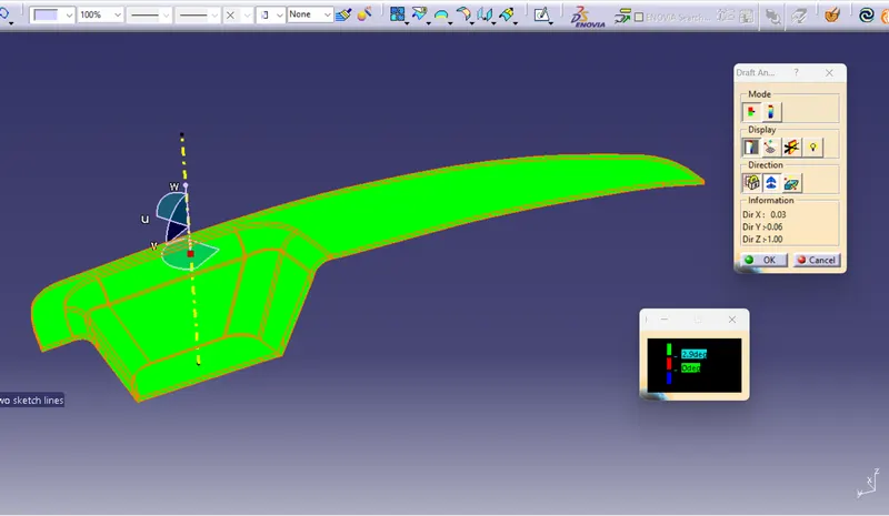
Screenshots of the solid model with the proper color code of the draft angle in various orientations (Isometric, Front, Side, and Top View):-
FINAL SOLID PART : -
PUBLICATIONS:-