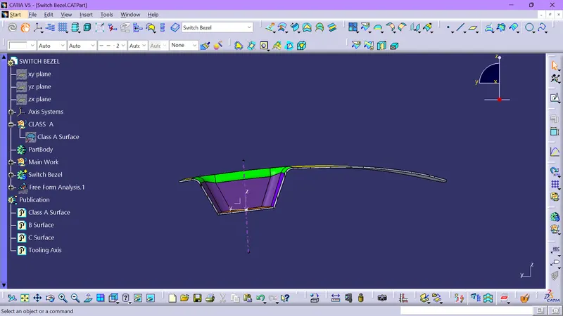
Week 9 - Challenge 2 - Switch Bezel Design
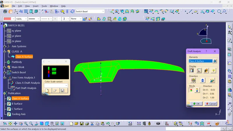
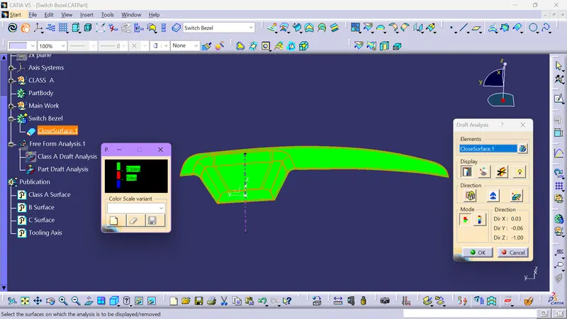
Draft Analysis
- It is the Analysis in which we analyse the Class A Surface for the Manufacturability or Mouldability
- In this We check whwther the pat can be mulded or not.
- Basic principle here is, Every wall should be at an angle of 0.5° to 7° to the Tooling axis.
- 3° is the nominal value
- 7° is for textured surfaces.
- 0.5° is minimum value, but it needs more investment (Generally not Preferred).
- We first keep the Axis system on the tooling axis of the part.
- Then select the part to be analysed.
- It shows colours, If its green the Tooling axis created is correct.
Tooling Axis
- It is an Axis in which we use for Moulding.
- In Simple Words it the Direction of movement of the core.
- Creation-
- First we Create a dummy axis for any reference purpose.
- We create it by Analysing the walls of the part.
- Bisecting method is also used in this.
- Prior we select any of two walls which are opposite and made a line along the direction
- Then a Bisecting line is created using those two lines as input.
- Again We select the third side and create two lines one on the side and another at the centre point of the botttom surface.
- And a bisecting line is created with these lines.
- At last Bisetting lines is created using these two bisectng lines as input.
- That Bisecting Line is considered as the Tooling Axis.
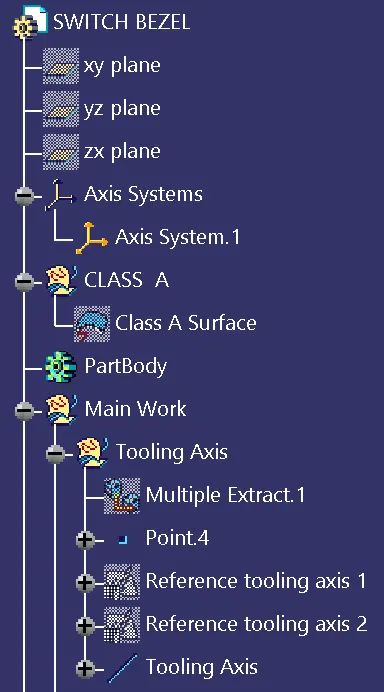
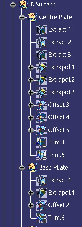
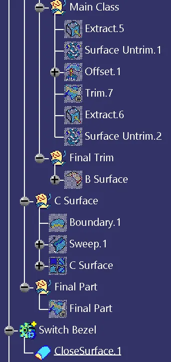
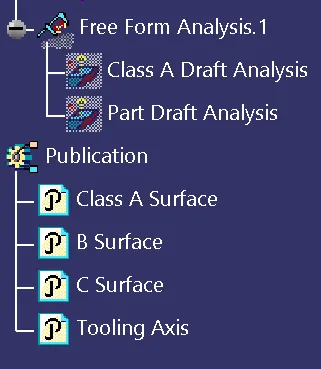
Tree Structure
Class A Draft Analysis
Part Draft Analysis
Orientation
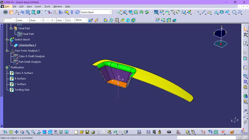
Isometric View
Top View
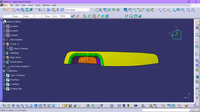
Side View
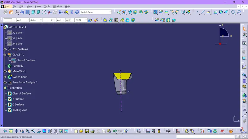
Front View