Week 9 - Challenge 2 - Switch Bezel Design
AIM:
To Create the Switch Bezel Plastic component through the given Class-A surface. To begin with, the tooling axis for the given Class-A Surface should be created meeting the requirements of the draft angle and also Create the Class-B Surface & Class C Surface. At the end perform to give thickness of the model.
TOOLIS USED:
Boundery
Join
Multiple extract
Trim
Surface offset
Draft analysis
Intersect
Surface sweep
Close body surface
DESCRIPTION:
CREATING TOOLING AXIS :
The Tooling Direction is basically the direction that the mold pulls a part. The mold is built in two separate piecs,basically. You have a Cavity side and you have the core side. The Core pulls apart from the Cavity and that's the dye line or the tooling direction.
Opwn the given CATpart file.
PUBLICATION :
Publication is done to the component to make it visible and navigate easily.
To publish the component go to tools> publication and then select the tooling axis and the class A surface.
A separate tree structure is formed under the main part.
DRAFT ANALYSIS:
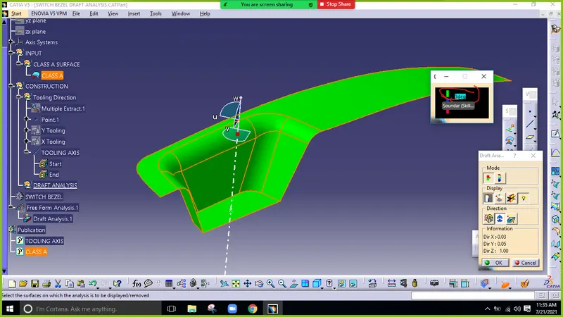
The Draft Analysis command enables you to detect if the part you drafted will be easily removed. This type of analysis is performed based on color rangs identifying zones on the analyzed element where the deviation from the draft direction at any point, corresponds to specifid values .
Before going to draft analysis go to customized view parameter > under mesh>check material and then click ok.
In the colour scale change the draft angle 3 degree.
The component changes to green in in dication of passing draft angle.
Use running point to check the angle on the component.
PROCEDURE:
Here the class A surface of the door switch bezel was provided as in OEMs. I created a class B & class C surfaces from the class A. Then I created a solid body of 2.5 mm uniform thickess using class A, class B & class C surface. Finally I successfully performed the draft analysis of the component. The steps I followed for the creation of this component are given below.
1. CLASS A SURFACE:
In automotive design, a class A surface is any of a set of freeform surface of high efficiency and quality. Class A surfacing is done using computer-aided industrial design application. Class A surface modelers are also called "digital sculptors" in the industry
Industrial designers develop their design styling through the A-Surface, the physical surface the end user can feel, touch,see etc.
Design check on Class A Surface:
After reciving class a for the SWITCH BEZEL check for the connectivity of the surface on it. If there is any disconnectivity, use join operation, multiple extract, multi section surface, boundary operation and disassemble.
Join operation:
Go to join command to join the disconnectivity of the surface. Give merging distance=0.003mm.
When there not connected, after reciving Class A surface, delete only the checking command of boundary operation and disassemble, When there are connected delete join operation, boundary operation and disassemble after the check. The check is over if any disconnectivity do not arise.
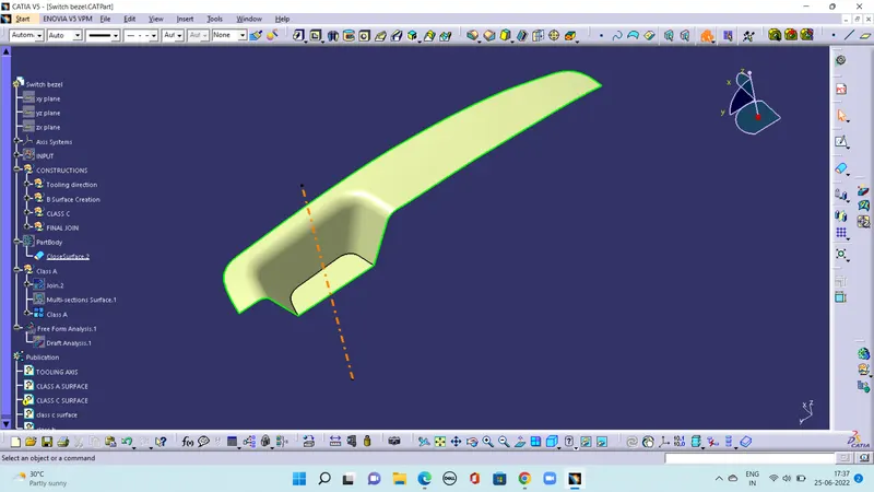
CREATING CLASS B SURFACE
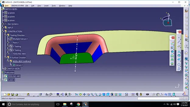
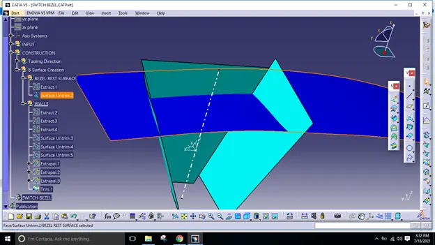
Extract the surface from the class A using multiple extract and untrim them.
use Extrapolate to make sure that all the untrims are properly intersected to trim and offset the surfaces to 2.5mm to create the thickness.
Trim the extra surface using trim command
Apply fillets to the model after creating the entire surface.
If the edges are outside the fillet value will be added to the thickness of the component and if the edges are in side, the fillet value will be subtracted from the thickness of the component, for instance the thickness fo the component is 2.5mm the fillet value is mm so the outside portion value should be and inner eges shuold be filleted to get uniform thickness.
perform trims one at a time so that it will be clear to understand.
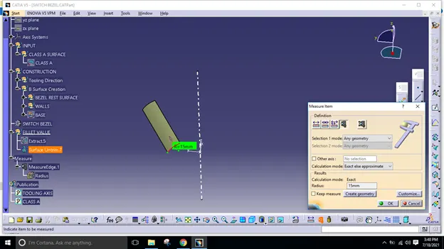
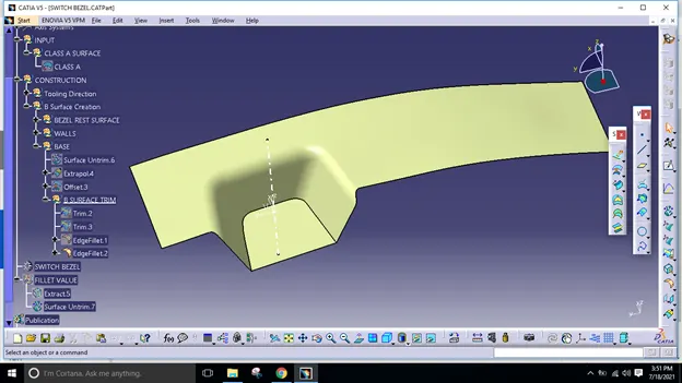
REATING CLASS C SURFACE
Extract the boundary from the class A surface using boundary command.
Using disassemble tool to divide the boundary as the boundary contains domains.
Use sweep command> choose profile type line >subtype as with draft direction> choose guide curve and draft direction >draft angle as 3 degree> preview.
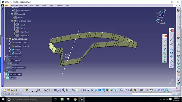
Closed Body Creation
- The Merged surface is then trimmed with B surface to from the closed surface.
- The Closed surface is then validated to find the irregularities along the edges and imperfections along the edges were then corrected using operation like extrapolate and surface trim
- This Closed surface is the outer skin of the switch bezel and finally the part is formed by Closed surface in Part design workbenbnch.
- The Final Part is measured to validate the uniform thickness of the part especially along the filleted edges.
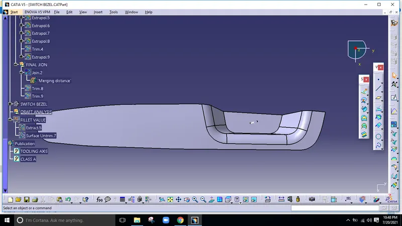
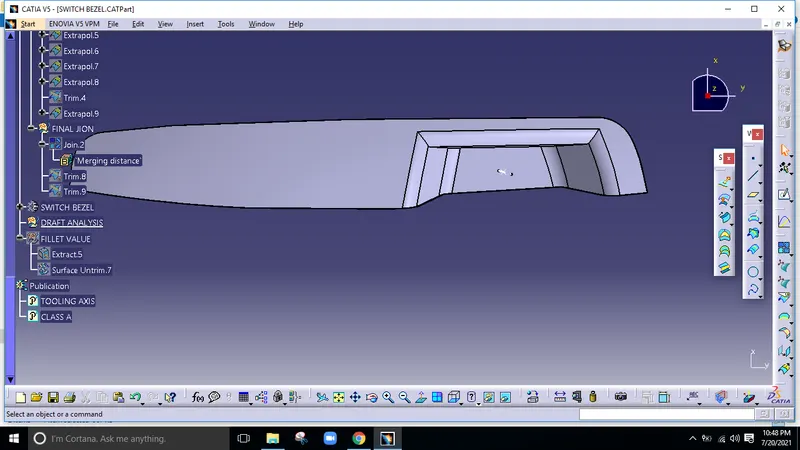
Different Views
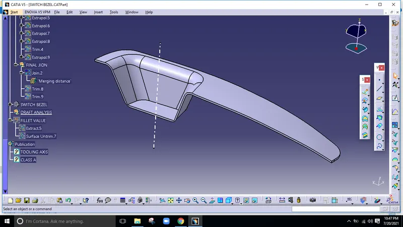
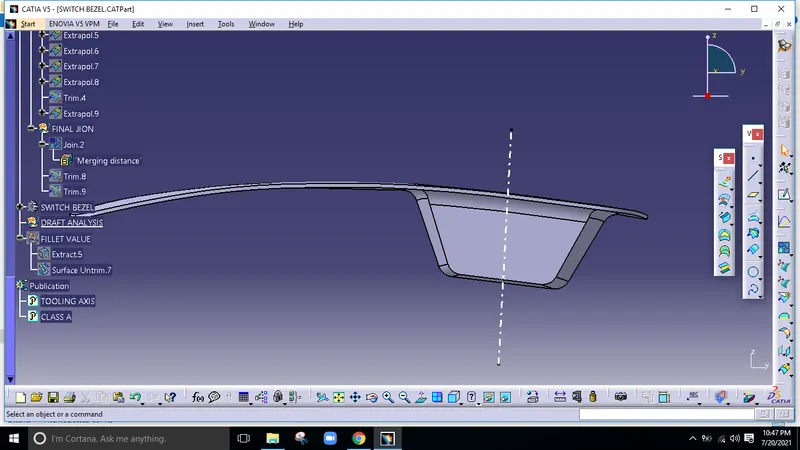
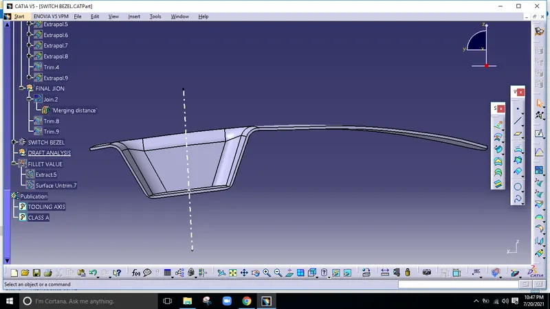
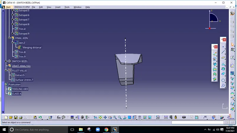
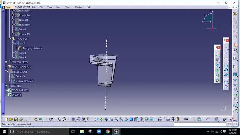
Draft Analysis
- The part created has to be changed to material mode in dispaly frame
- Then by enabling compass definition the axis system is pan along the direction of the part and aligned in line with the toling direction
- Lock Direction is applied that fixes the compass and then the mode dialog box is formed by snapping at any point on the part
- The Color Codes are classified and Draft angle are applied
- Then the Running point analysis is used to hover around the part to analyze the permissible draft angle and the analysis is saved