Week 9 - Challenge 2 - Switch Bezel Design
Detailed Report:
Tooling Axis:
1)By visual analysis, the base surface is the best place for the tooling axis.
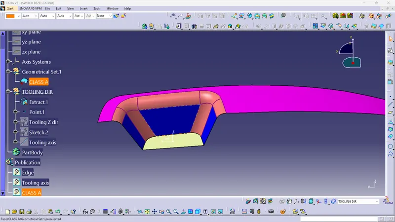
2)Created a sketch to intersect the switch bezel surface to the ZY plane
- Extract the base surface.
- BY creating a point at the centre of the base surface using surface type.
- Insert an axis.
- create a positioned sketch in the ZY plane at the point created in the middle of the base surface.
- Intersect the surface into the plane.
- Draw two lines at the inclined lines and create a Bisecting line between those lines.
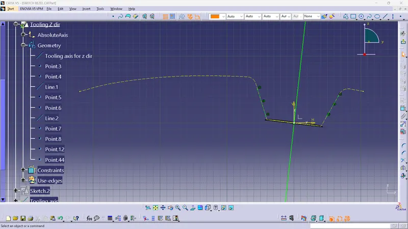
3)Created a sketch to intersect the switch bezel surface to the ZX plane
- create a positioned sketch in the ZX plane at the point created in the middle of the base surface.
- Intersect the surface into the plane.
- Draw a line at the inclined lines and draw the other line from the middle point.
- The angle difference between the two lines should be 6 deg(min draft angle).
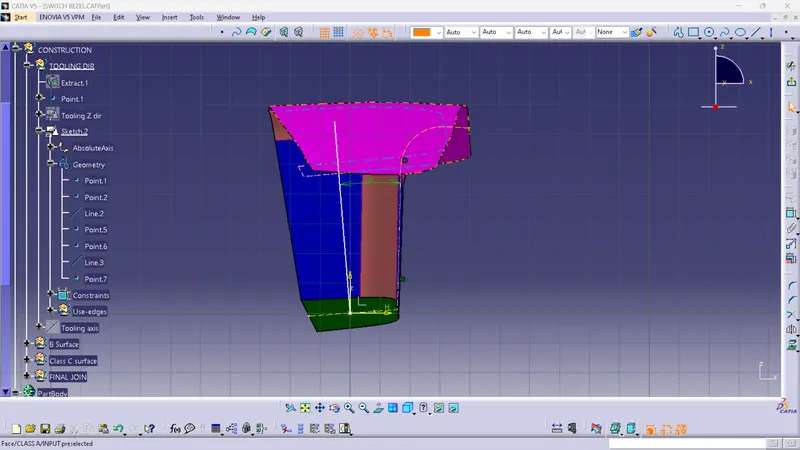
4)Then draw a bisecting line between that two lines. Use bisecting type line and select the two lines we draw. This is the tooling axis of this surface
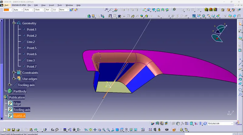
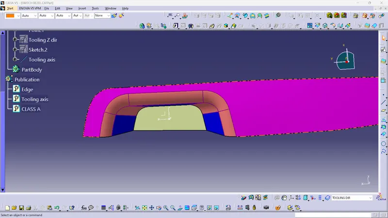
Draft analysis of Class-A surface:
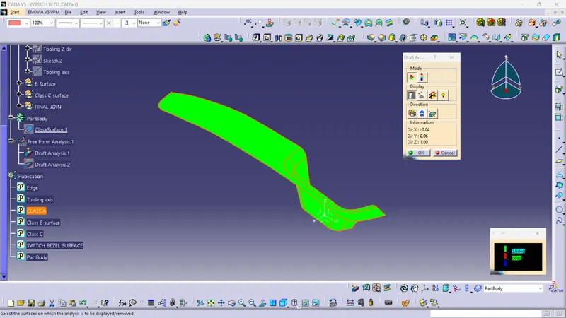
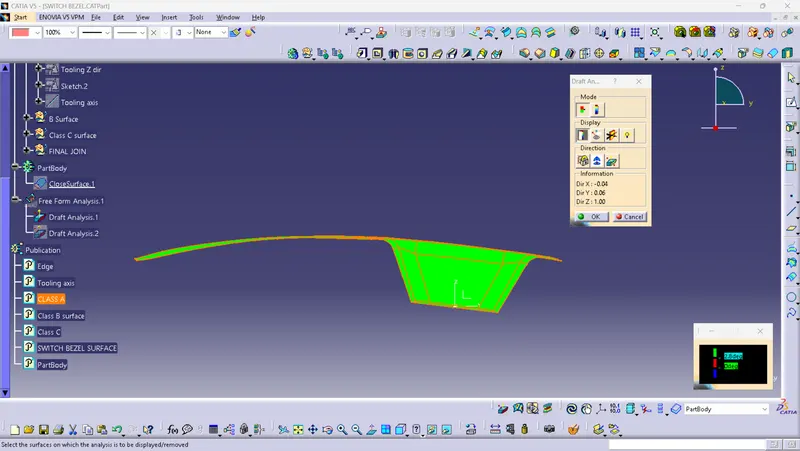
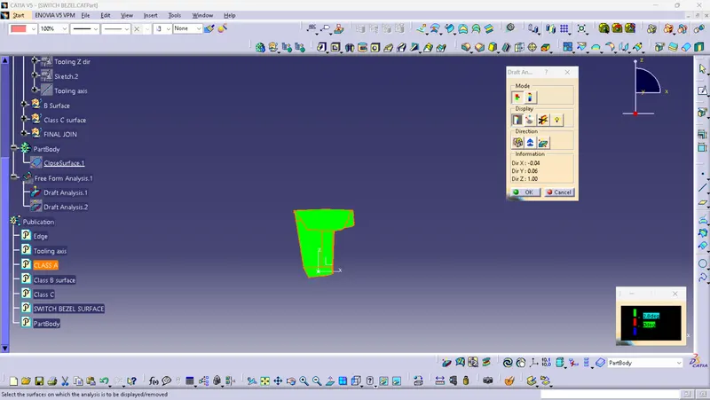
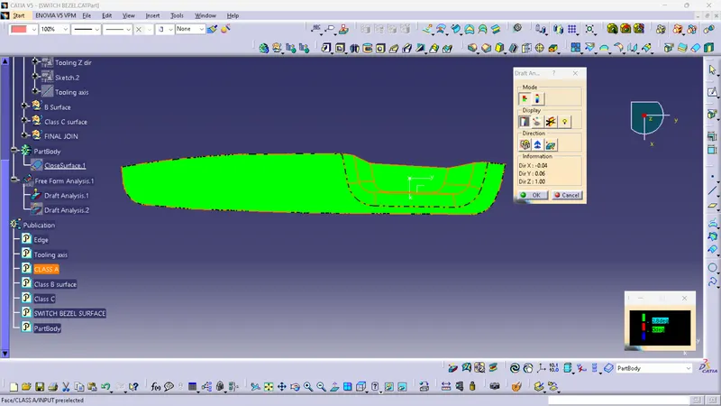
- Selected Draft analysis
- Selected compass to define the new drafting direction.
- Select and drag the compass and place it in the tooling axis.
- Select the lock and lock the compass.
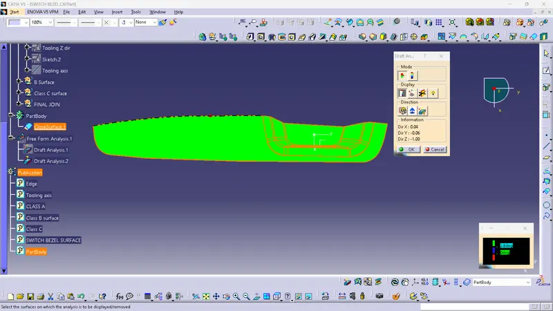
- Move the cursor and place it over the A surface and click on it.
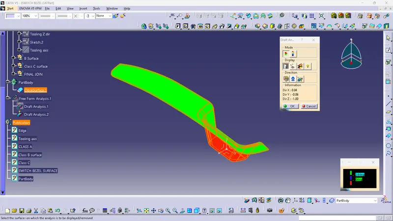
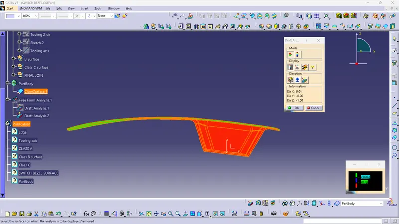
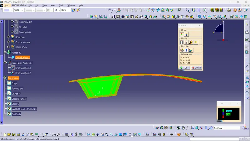
- It turned to Green colour. Which indicates surfaces are at an angle of more than 2.8deg
Draft analysis of the final plastic component:
- Selected Draft analysis
- Selected compass to define the new drafting direction.
- Select and drag the compass and place it in the tooling axis.
- Select the lock and lock the compass.
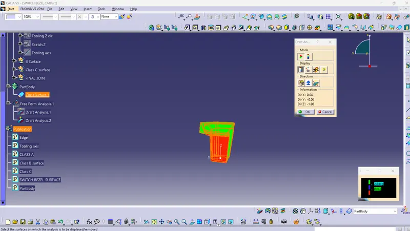
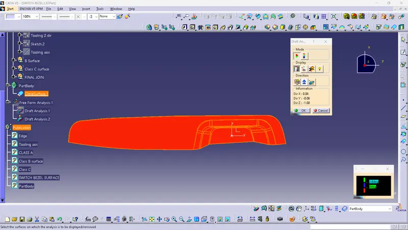
- Move the cursor and place it over the Final solid body and click on it.
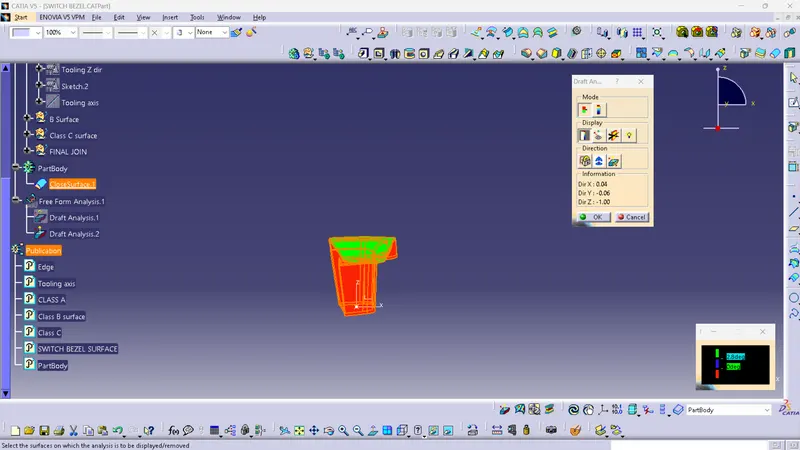
- The surfaces that turned Green colour indicate the surfaces are at an angle of more than 2.8deg.
- The surfaces that turned red indicate the surfaces are at an angle of less than 0deg.