Week 9 - Challenge 2 - Switch Bezel Design
Switch Bezel Design
Aim: To design a Switch bezel by using the given Class A surface and conduct draft analysis on it
Steps Involved in Creation of Switch Bezel Design
Step 1 : Creation of Tooling Axis
Pan around the Class A surface and find a surface and point where the tooling can done. After finding the surface extract the surface and add a point on the ceter of the surface. Using Intersection command. draw dummy tooling axis of both X and Y axis bisect those two axis you will get the Tooling Axis
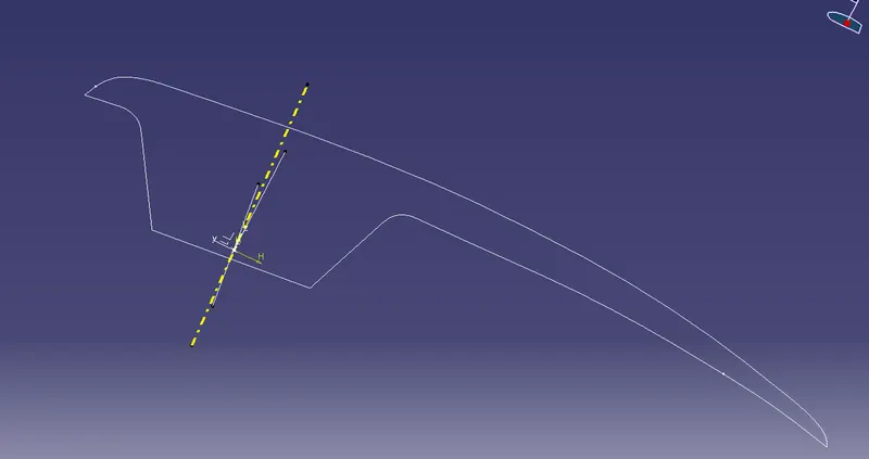
The yellow dotted line is tooling axis two lines arround it are the dummy tooling axis for X and Y direction
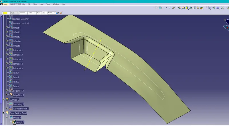
Step 2 : Creation of Surface B
When Creating the B surface avoid complex edges and extract the flat surface untrim it , extrapolate and trim those surface you get a identical surface find the filet radius and fillet the edges and offset it to 2.5mm which is asked in the question
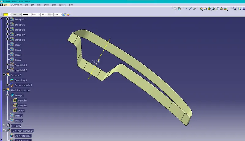
Step 3 : Creation of Class C surface
Extract the border of the Class A surface and smoothen the curve to make it clean and Sweep the border along the tooling axis with a draft angle to achieve minimum draft
Step 4 : Joining Class A with Class C
Join class A Surface with Class C surface
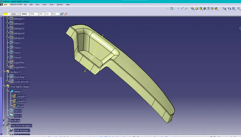
Step 5: Trim Joined surface with Surface B to get the final output
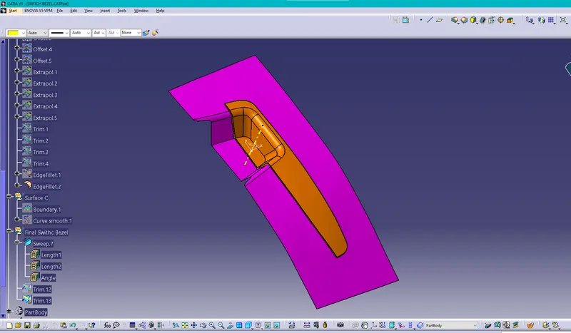
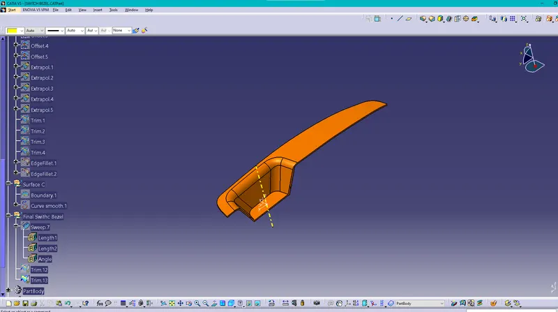
Step 6: Convert the surface into a solid
Use close body command in the part workspace and convert the closed surface into a solid
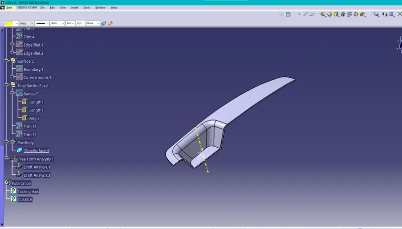
Results
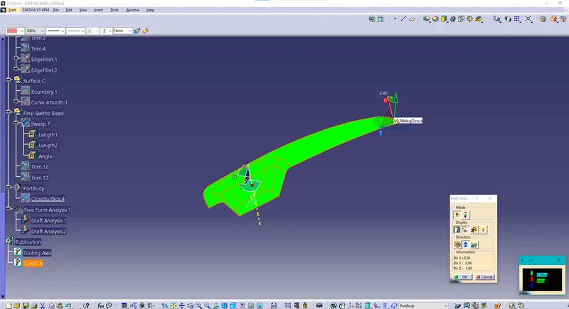
Draft analysis of the solid
This is done to check whether a draft angle is maintained throught the solid
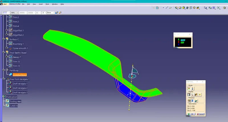
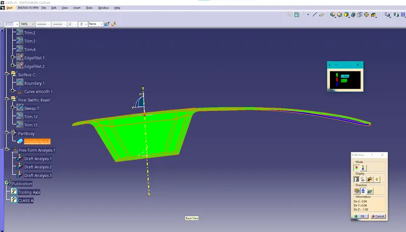
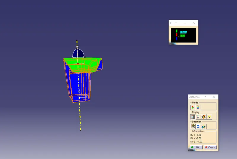
Draft Analysis of Class A