Week 9 - Challenge 2 - Switch Bezel Design
AIM
To create the switch bezel a plastic component through the given CLASS-A surface by creating the tooling axis that meets the requirements of the draft angle and to perform the draft analysis at the end once we have the solid part.
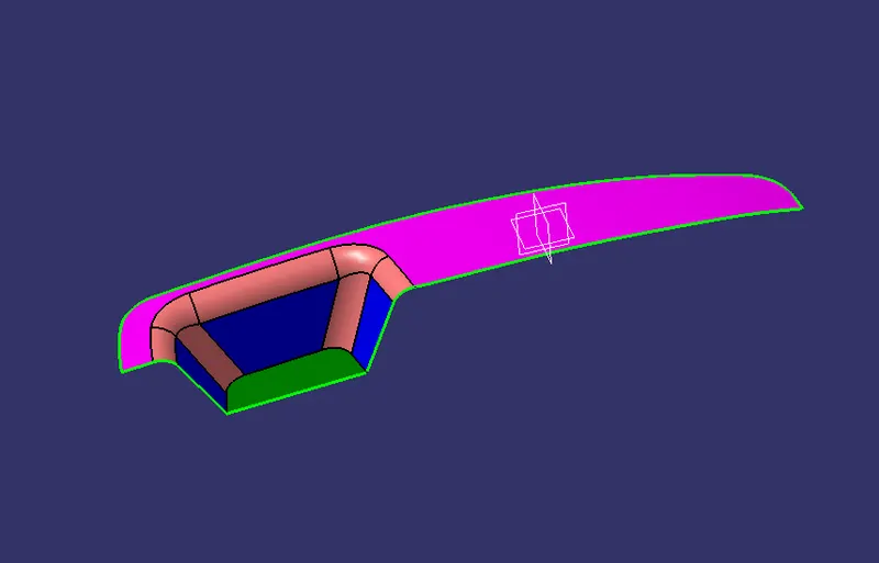
GIVEN CLASS-A SURFACE
STEPS FOLLOWED:
- First, we need the tooling axis to perform the draft analysis but for that, we need to extract the surface which will be a problem for draft analysis.
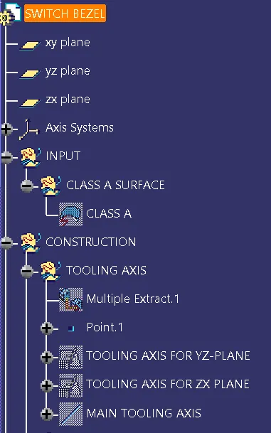
- in this case, we only have three walls first we will create the tooling axis for YZ-PLANE.
- In this we are going to create the tooling axis by using the sketch for that first we need to project the 3D elements of the CLASS-A surface and then draw a line along the projected lines and then by using the BISECTING line create the tooling axis for the YZ-PLANE
- The same is to be followed for ZX-PLANE but there is only one face so project the 3D elements of the CLASS-A surface for that and create the angle line from the projected element for around 3-4 degrees.
- And at last, create the TOOLING DIRECTION by using a dummy tooling line which we created in YZ-PLANE & ZX-PLANE by bisecting the line and finally, we get the main tooling axis.
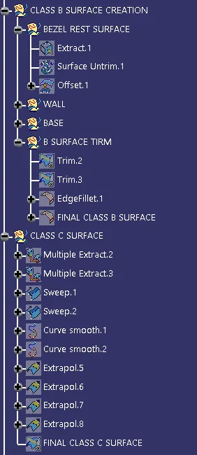
- After creating the main tooling axis we need to create the CLASS-B SURFACE by offsetting the CLASS-A SURFACE for that we need to extract the face that is highlighted in the pink colour and then untrim the extracted face and offset is done.
- Next, the walls are extracted and for these walls, untrim is done after that extrapolated each wall to intersects with each other and trimming is done after that the edge fillet is given concerning the CLASS-A surface.
- And the base has been extracted and untirm is done followed by extrapolated and offset and the final trim takes place.
- Now C-SURFACE is created by using the boundary of the CLASS-A SURFACE and the boundary is extracted and then by using the sweep command the CLASS-C SURFACE is now created with the draft angle of 3 degree with the help of the tooling direction
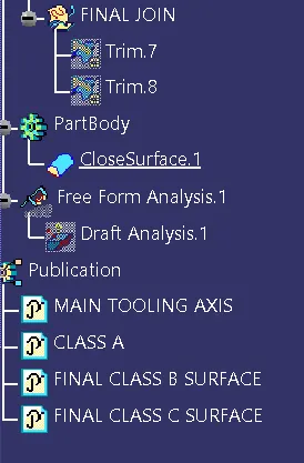
- Now the CLASS-A and CLASS-B, CLASS-C surfaces are joined together by trimming.
TREE STRUCTURE
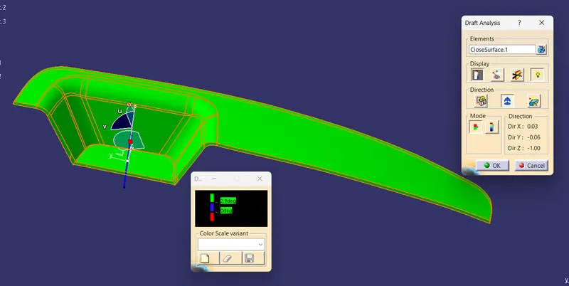
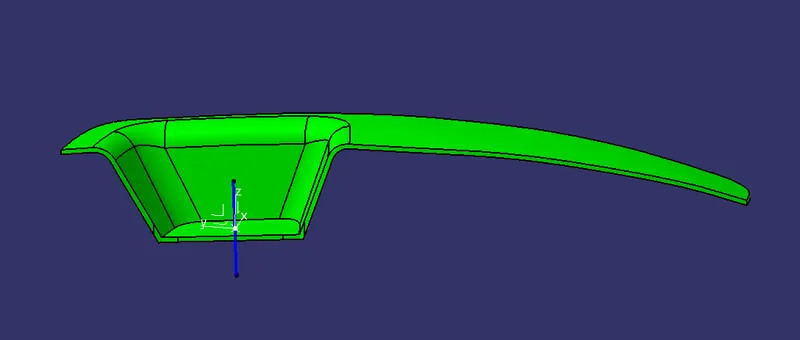
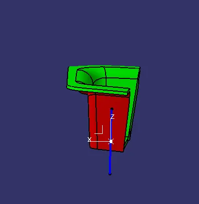
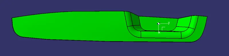
DRAFT ANALYSIS FROM DIFFERENT VIEWS
ISOMETRIC VIEW
FRONT VIEW
SIDE VIEW
TOP VIEW
DRAFT ANALYSIS
CONCLUSION
In this exercise I had learnt how to create the tooling axis on a complex surface and how to create the smooth surface by using the smooth curve to create the smooth surface.