Week 9 - Challenge 2 - Switch Bezel Design
STEP 1: The connectivity of the Class A Surface was checked using the JOIN command.
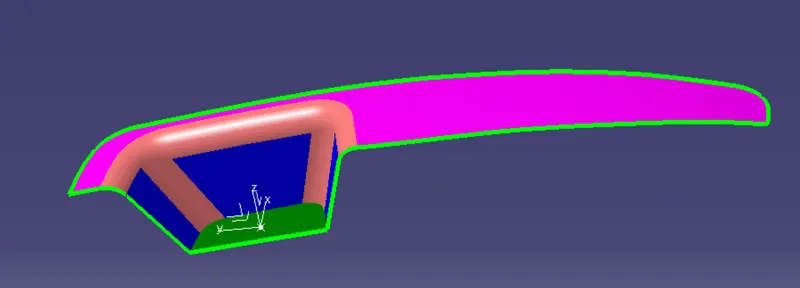
Step 2 :
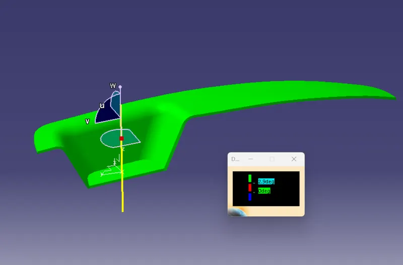
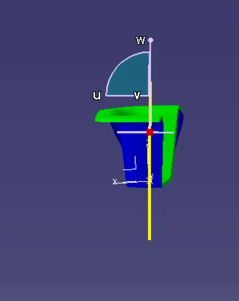
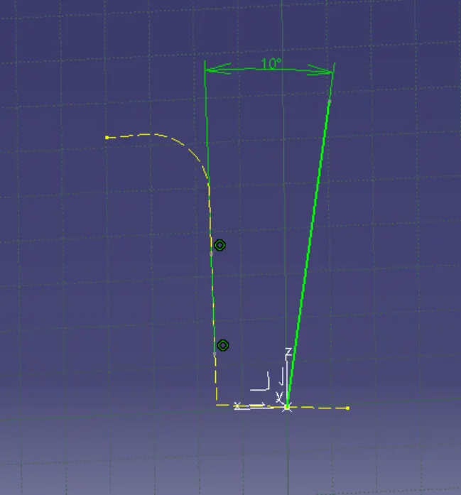
The tooling axis was created using the bisection of two lines. These two lines are the intersection of class A with a plane about a chosen point. This chosen point was taken on the flat surface. The first line was perpendicular to the flat surface. The second line was made at 10 degrees from the side wall which is intersecting at a plane as shown.
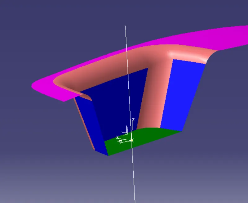
The final tooling axis:
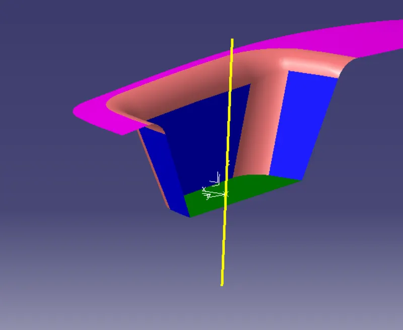
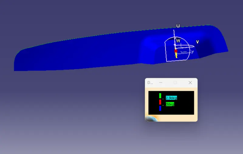
Step 3: Draft analysis was done about the tooling axis.
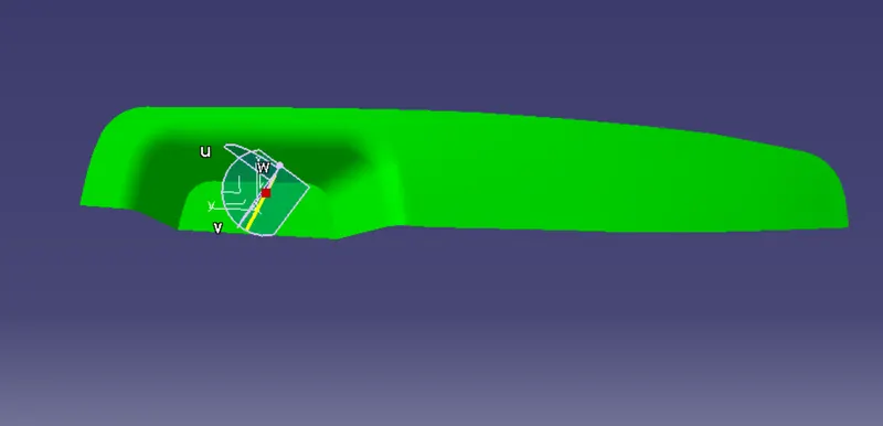
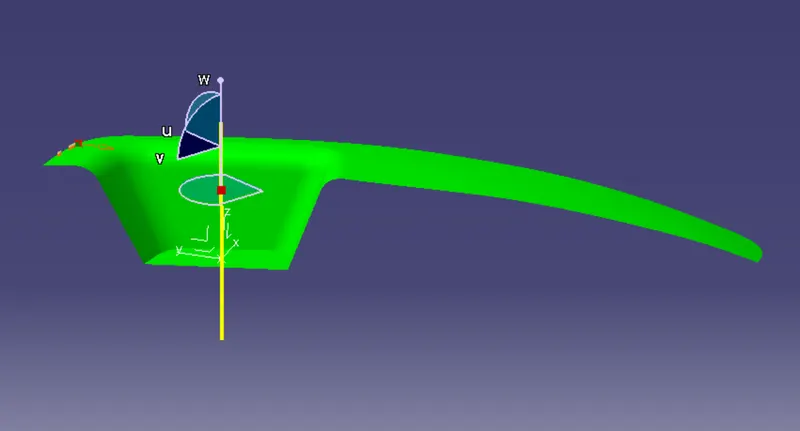
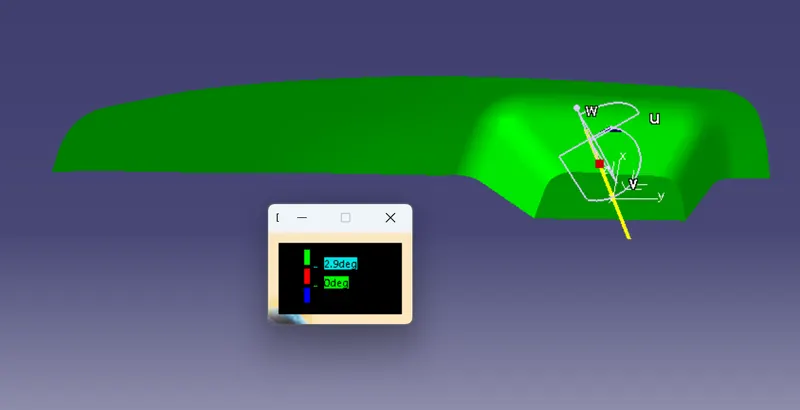
Step 4: An offset of class A was made below it by selecting individual surfaces. These surfaces went through extract, untrim, offset, and then trimmed together. This is now the class B surface.
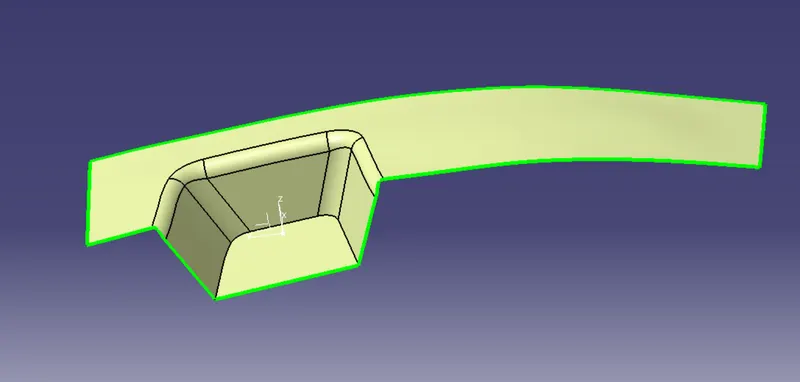
Step 5: A boundary of Class A was made and then then it was swept at 3 degrees along the draft direction using the SWEEP command and WITH DRAFT DIRECTION. This is class C.
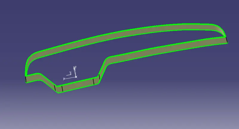
Step 6: Then Class A and Class C were joined.
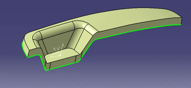
Step 7: Then Class A+C was trimmed with Class B.
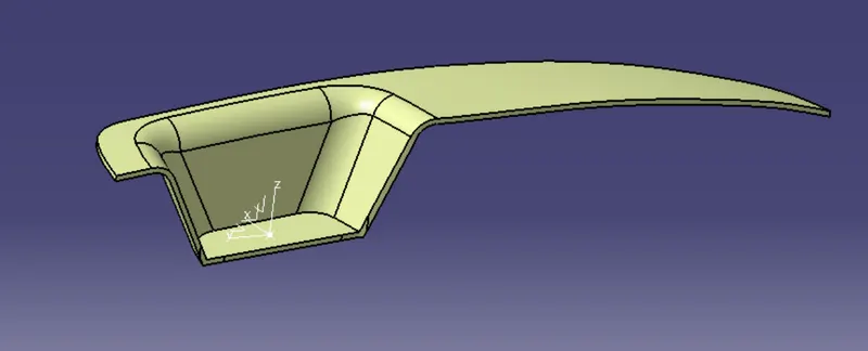
Step 8: The surface was made into a solid using the Close Surface command in the mechanical part design workbench.
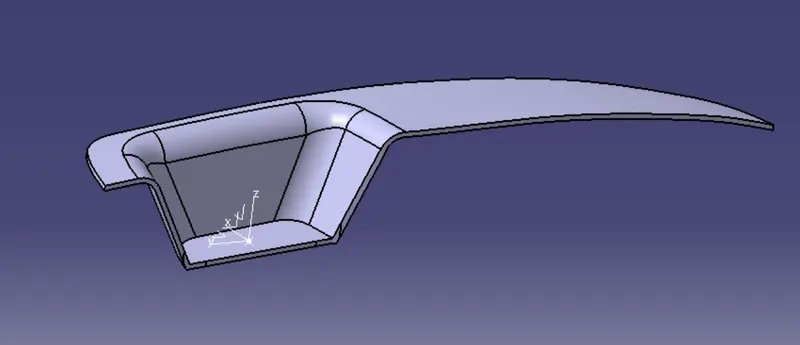
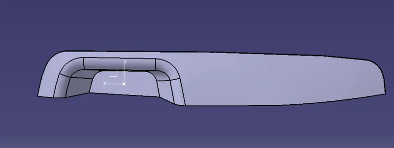
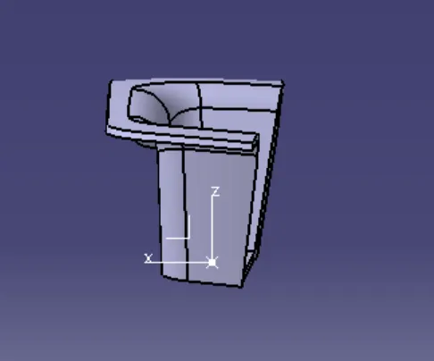
Step 9: Again draft was analyzed.