Week 9 - Challenge 2 - Switch Bezel Design
AIM:
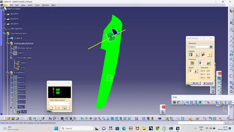
Create the Switch Bezel Plastic component through the given Class-A surface. To begin with, the tooling axis for the given Class-A Surface should be created meeting the requirements of the draft angle and at the end perform the Draft analysis on the model.
Initial Checking
Verification of Class A Connectivity
Boundary Verify the Class A Surface's connectivity. Use the connect command to ensure no gaps between the components. By using the border command or by visually inspecting it, we can check it.
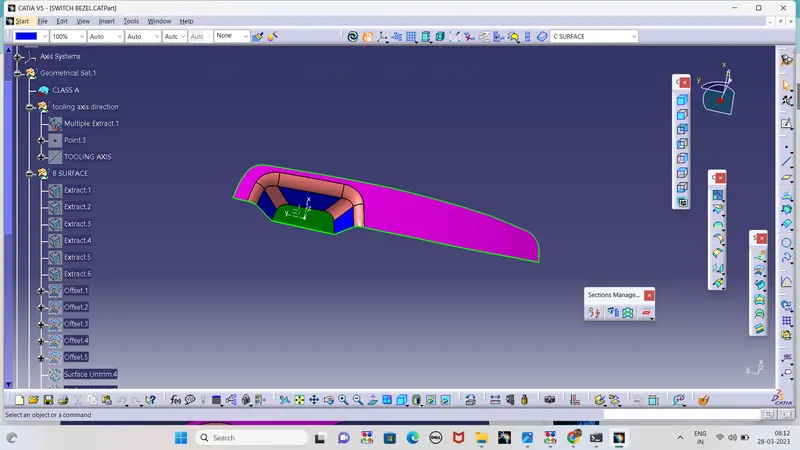
Tooling Axis
- The flat face is first wxtracted and a point is created on it
- Using Normal surface method a line is drawn in the Z direction and it is considered as a Tooling Axis
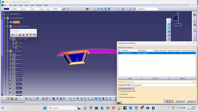
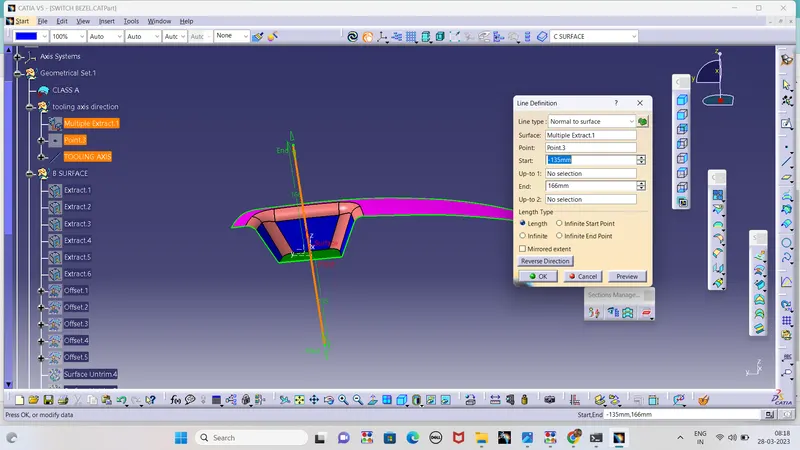
DRAFT ANALYSIS
A SURAFCE
B SURFACE
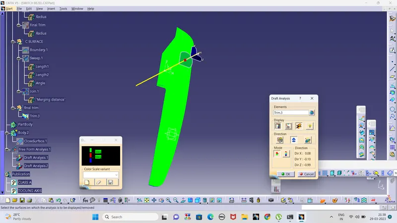
CLASS B SUFACE
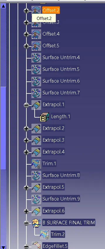
- The Required faces from the class a surface are extrcacted and offseted to 2.5mm
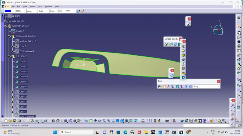
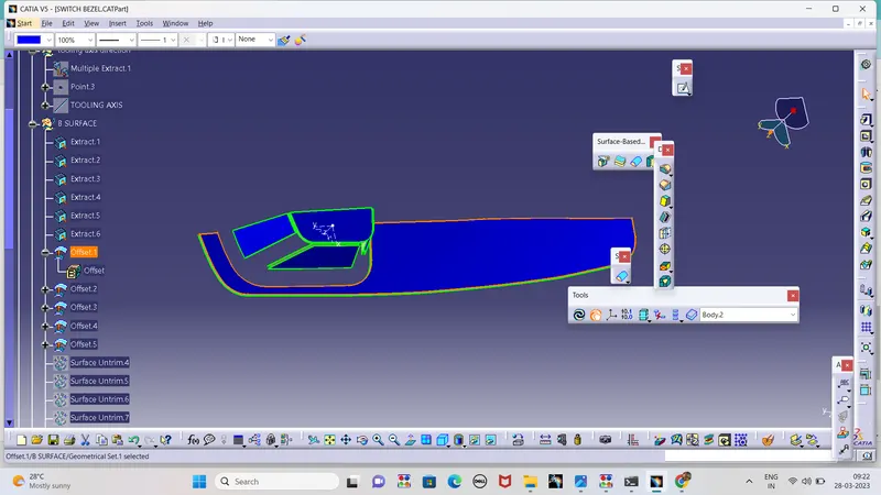
- Then the extracted surface is untrimmed and it is exterpolated to 20mm
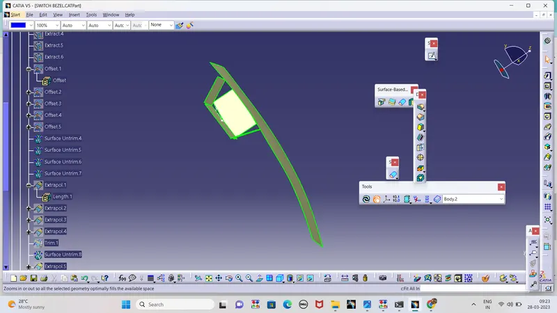
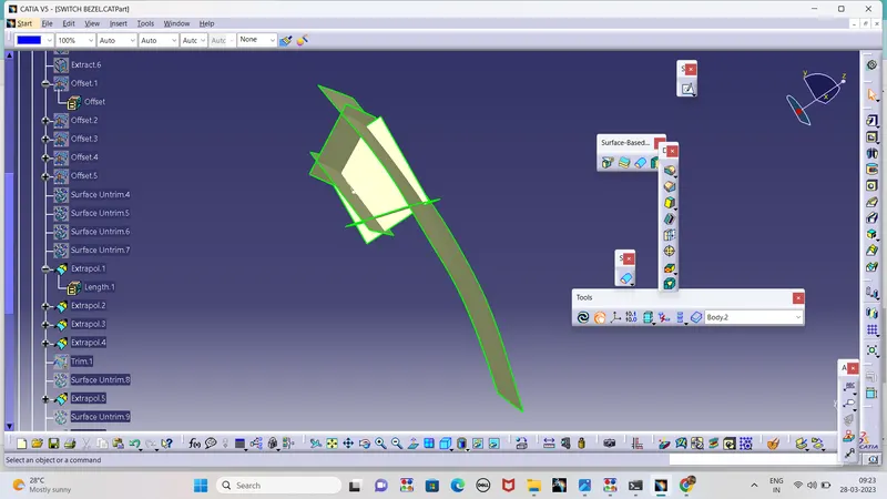
- The trim command is performed in the exterpolated bodies where the class b surface is obtained
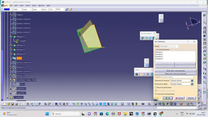
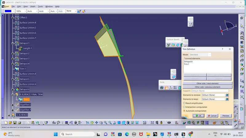
- The required fillet is given to the Sharp edges of Class B surface
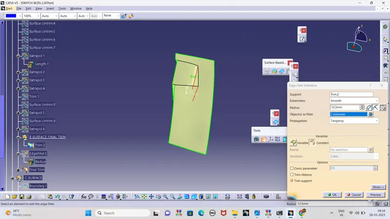
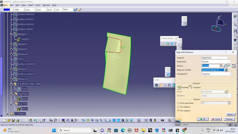
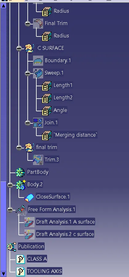
CLASS C SURFACE
- The Edges of the Class A Surface is selected by using the boundary command
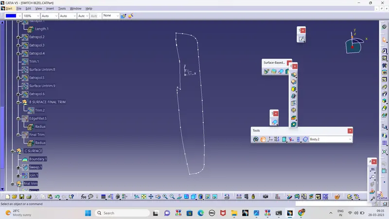
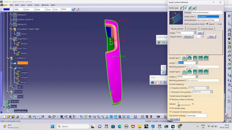
- The sweep operation is done by selecting the boundary as a guide curve
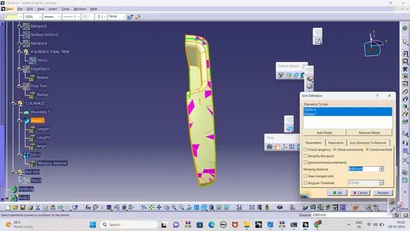
- Class A surface and C surface are joined by using the join Command
- The Joined Part is Trimmed with B surface and the final output is obtained
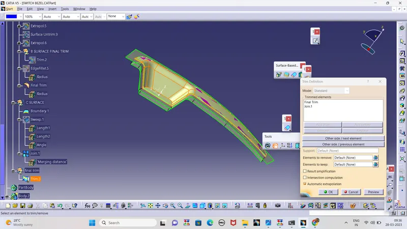
- The created C surface is checked By Dynamic Sectioning
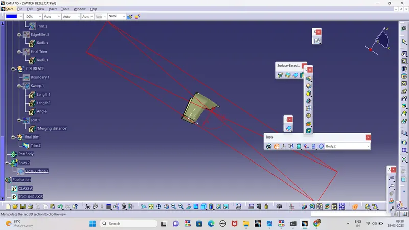
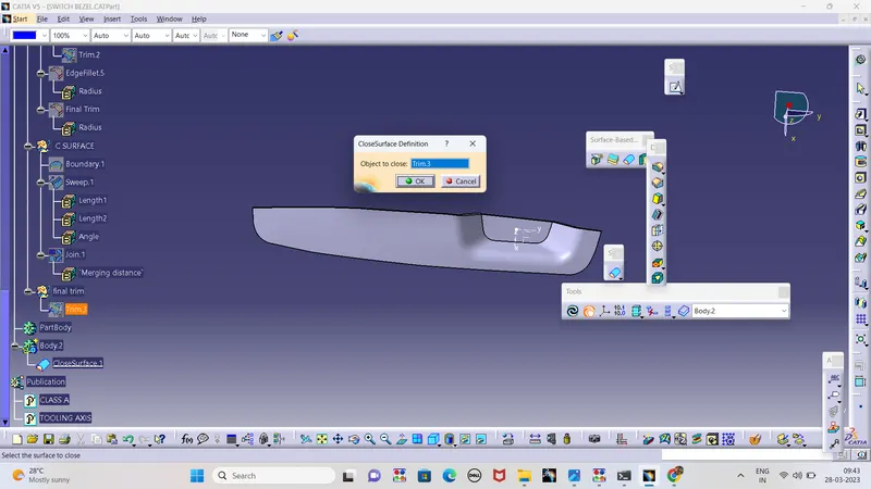
PART BODY OPERATION
The Surface Model is converted to a part body by using closed surface method
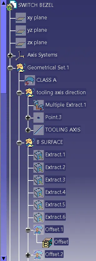
TREE STRUCTURE
PART ORIENTATION
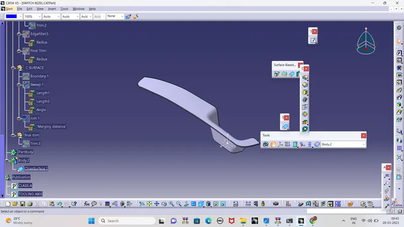
- Iso
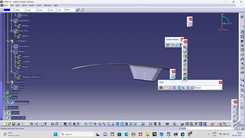
- Front
- top
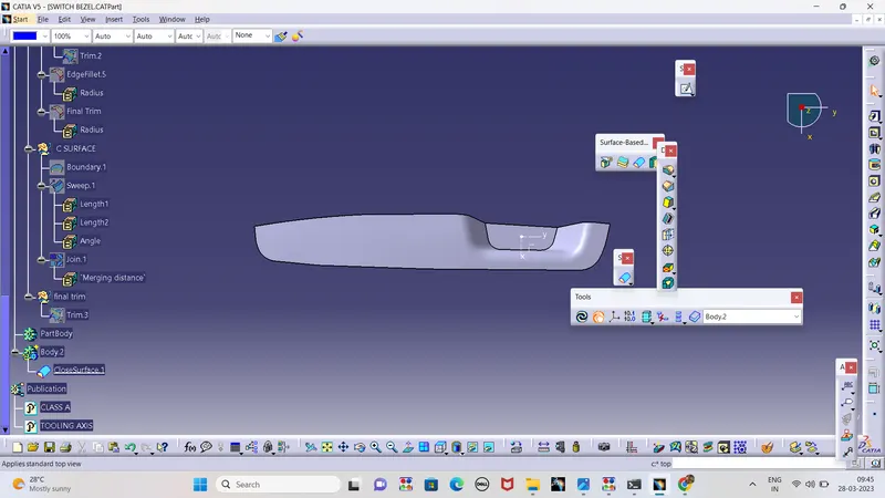
- side
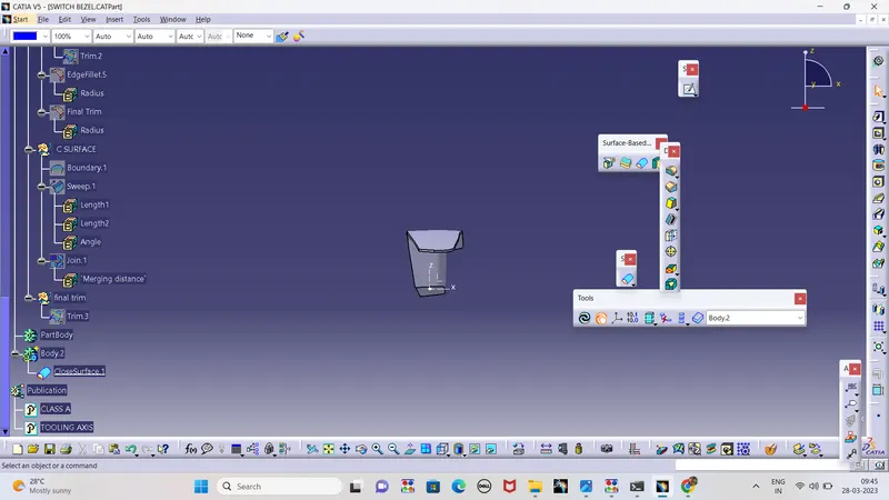
Conclusion
The Part body is created from the Given A surface ,the required attachments and image's are added