Week 9 - Challenge 1 - Base Bracket Design
Aim
To Create the Base Bracket Plastic component through the given Class-A surface. To begin with, the tooling axis for the given Class-A Surface should be created meeting the requirements of the draft angle and at the end perform the Draft analysis on the model.
Requirement
Thickness of Plastic Part - 2.5 mm
Objectives
- Explaining the draft analysis and the tooling axis creation
- An explanation should be given on the way of creating the tooling axis.
The given class A surface
A SURFACE
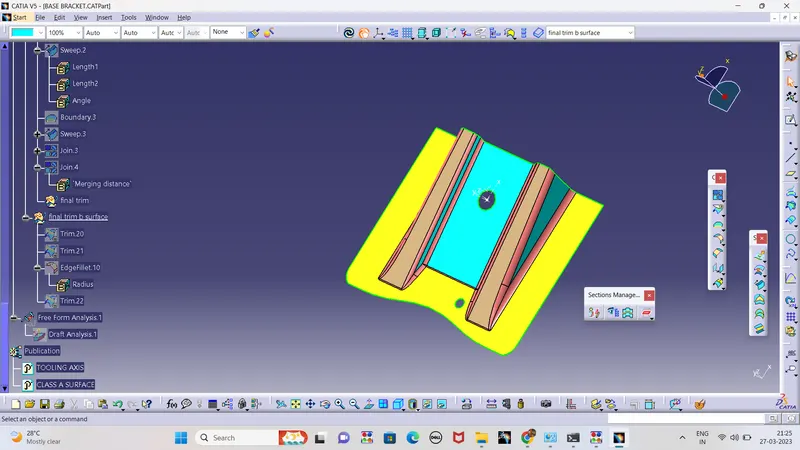
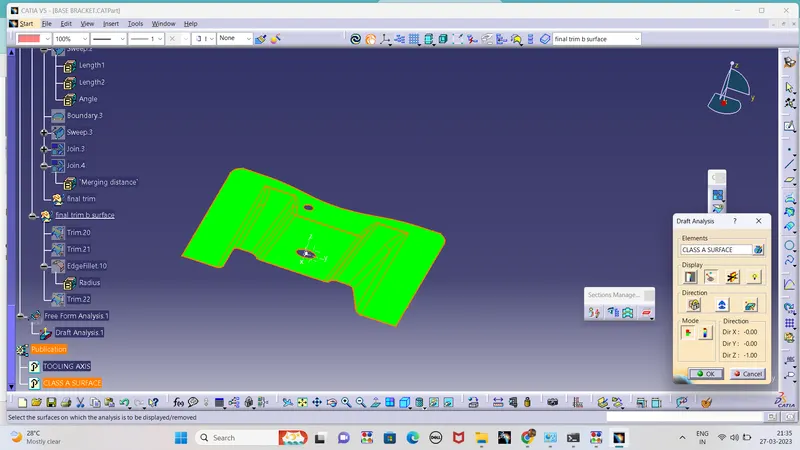
Draft analysis
The draft angle is the angle between the normal to the surface and the direction of the pull of the tooling during the molding process, The draft analysis tool to evaluate the draft angle of a product and adjust it accordingly.for the ease of manufacturing process. its is one to three degree allowed as maximum, or else the manufuring will be hard.
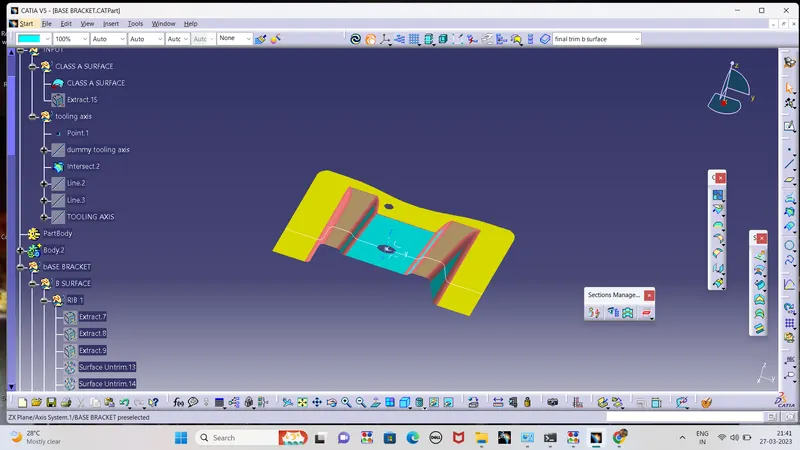
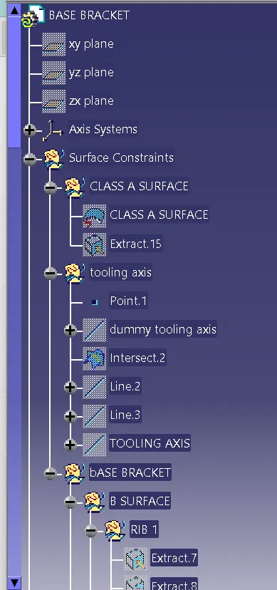
Tooling axis
the tooling axis is axis that defines the direction of the mould and cast to be joined for the preparation of the die.
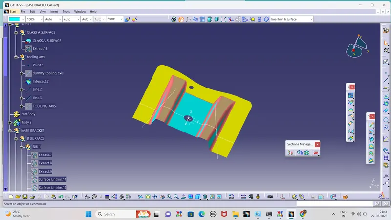
the bisecting method is said to be the choosing the line of direction in by bisecting .
A intersection is created in th zx plane in order to to create the tooling axis
lines are drawn from the parallel vertices (parallel to the tooling direction) in order to create a bisecting line
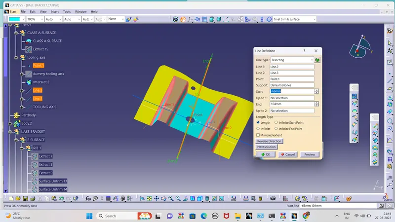
B surface
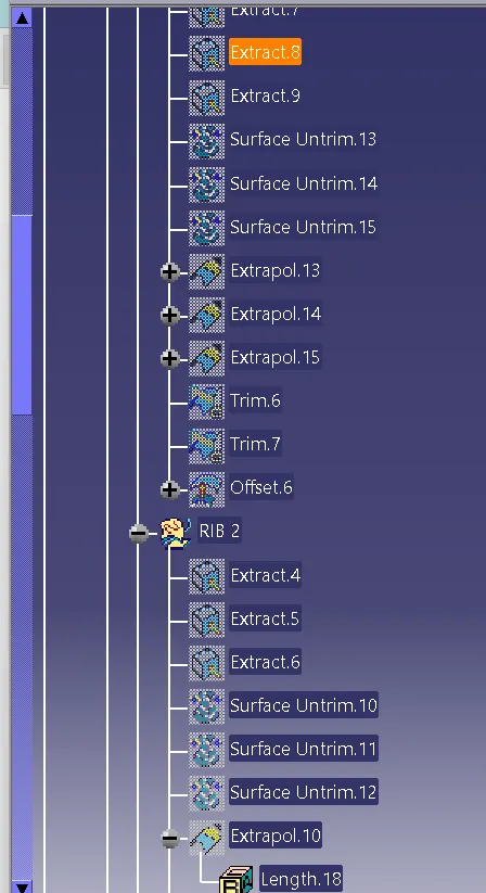
Rib 1
- The required faces for creation of B surface Of Rib 1are extracted from the A surface
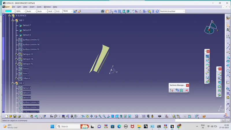
- Ater the Surfaces are extacted the extracted surfaces are untrimed
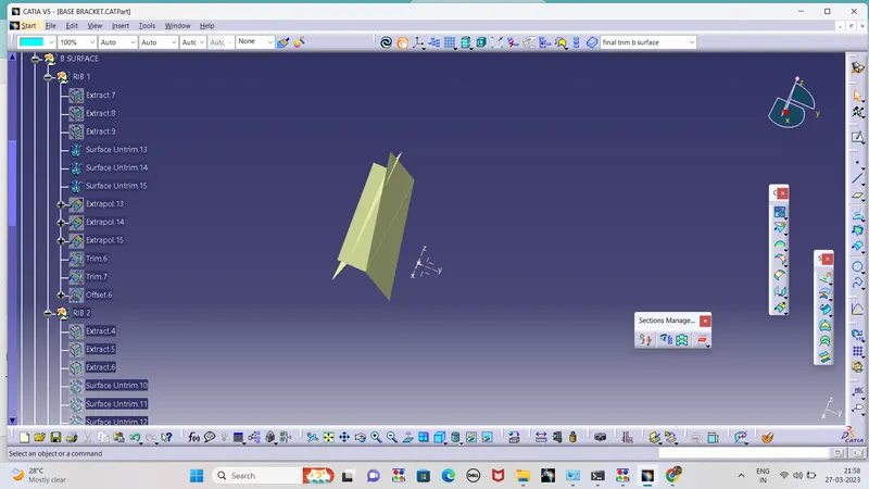
- It is then exterolated to 10mm and the trim opertaion is prformed in the faces to obtain the rib 1
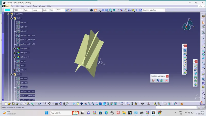
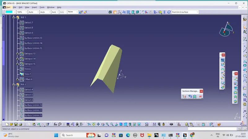
- the created surface is offseted to 2.5mm
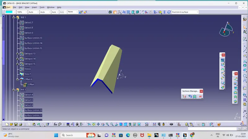
Rib 2
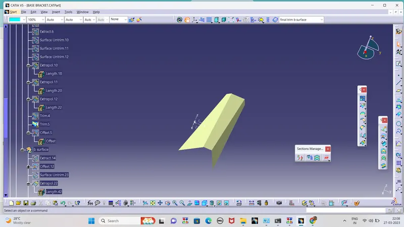
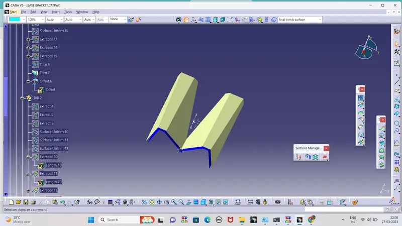
- The sane method used to form rib 1 is used to form rib 2 and it is offseted to 2.5mm
B SURFRACE 1& BASE
The B surface and the base are created as same as the 2 ribs
- The surface is first extracted from the A surface
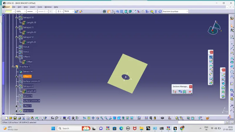
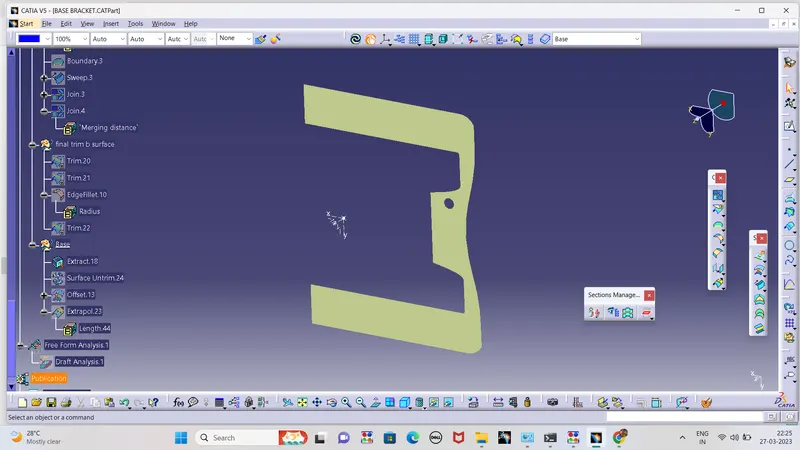
- The surface is offseted and the untrim operation is performed
Untrim
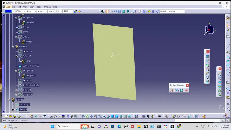
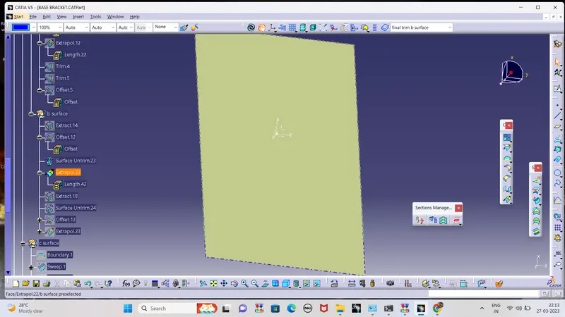
Offset
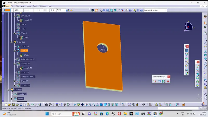
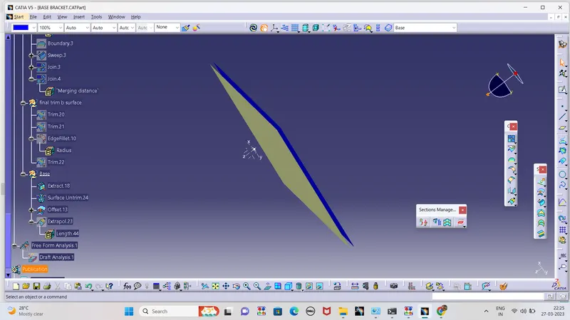
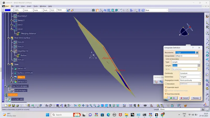
- The surface is then exterpolated to 10 mm
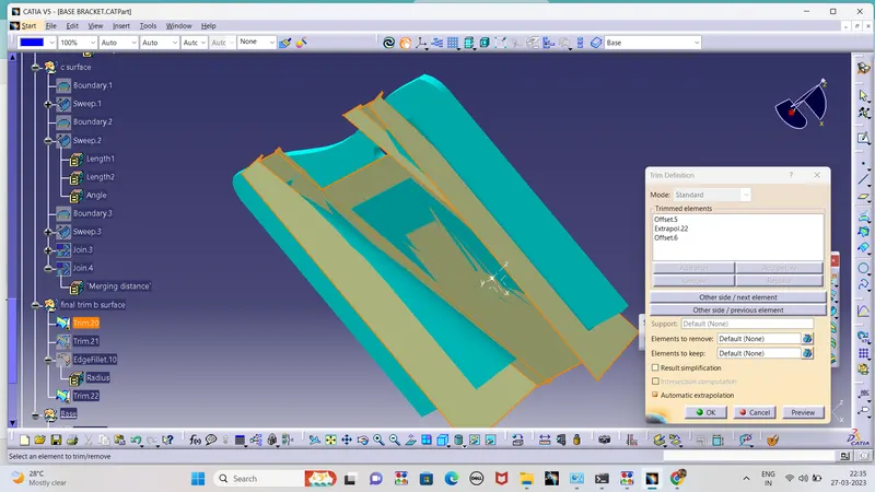
The Ribs are trimmed with the Bsurface 1 and the base and Class B surface is Obtained and a fillet of 2.4 mm is given to the sharp edges of B surface
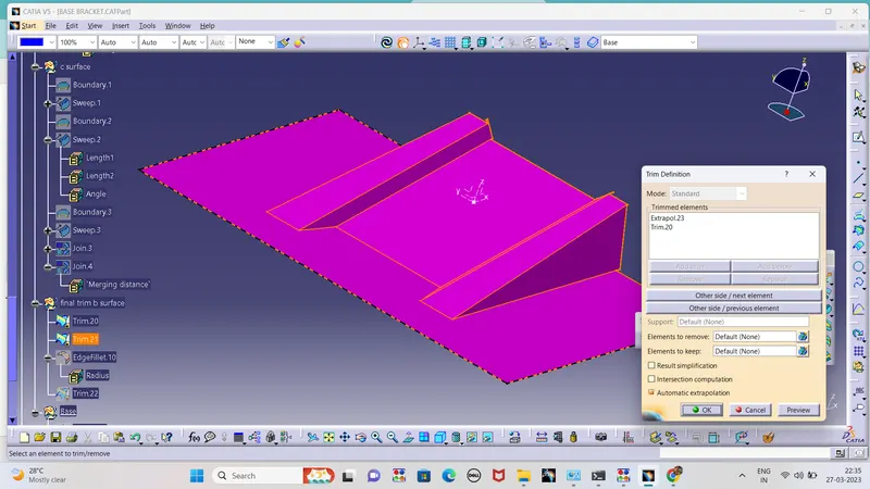
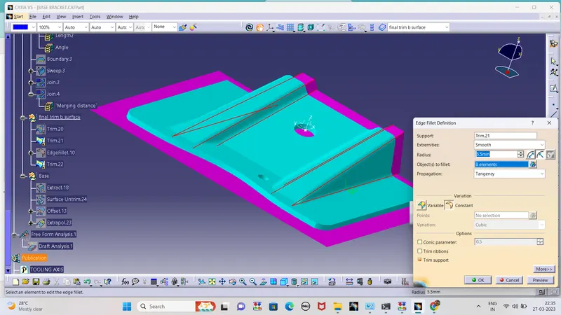
CLASS C SURFACE
- A BOUNDARY IS CREATED in the edge of the class , the sweep command is used to craete the c surface
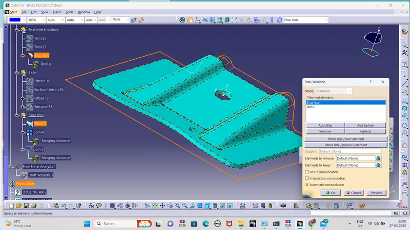
- The C surface And the A surface are joined using the join command and it is then trimmed with b suface in order to obtain the final object
- Boundary
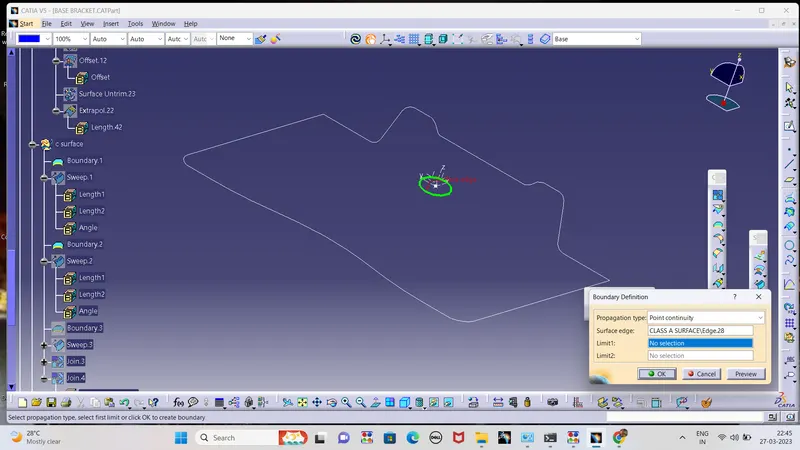
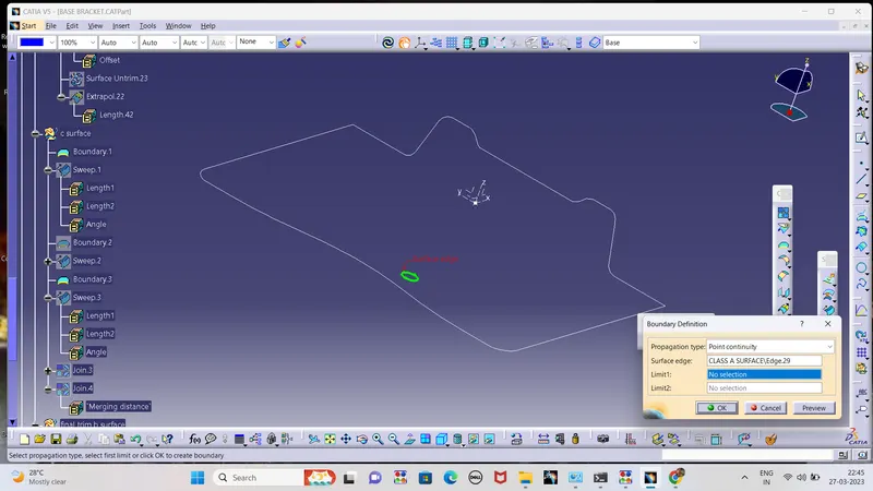
- Sweep
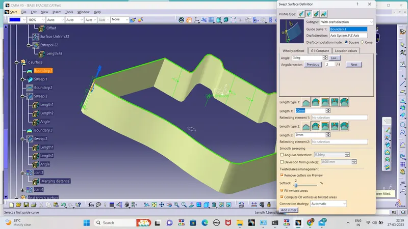
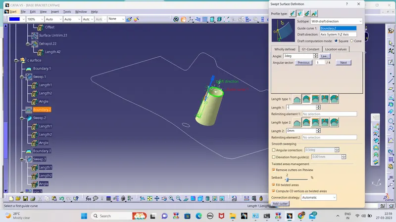
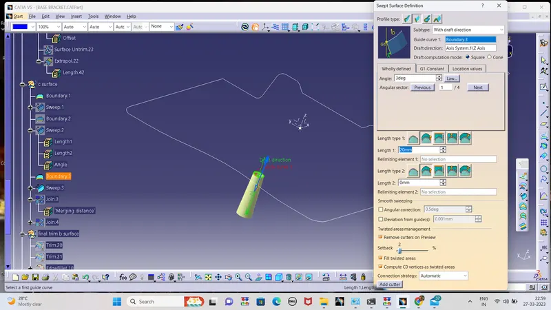
- Join
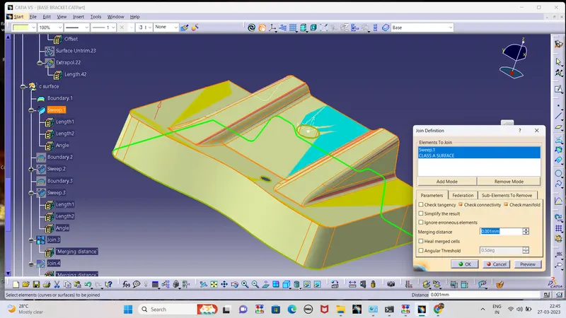
Trim
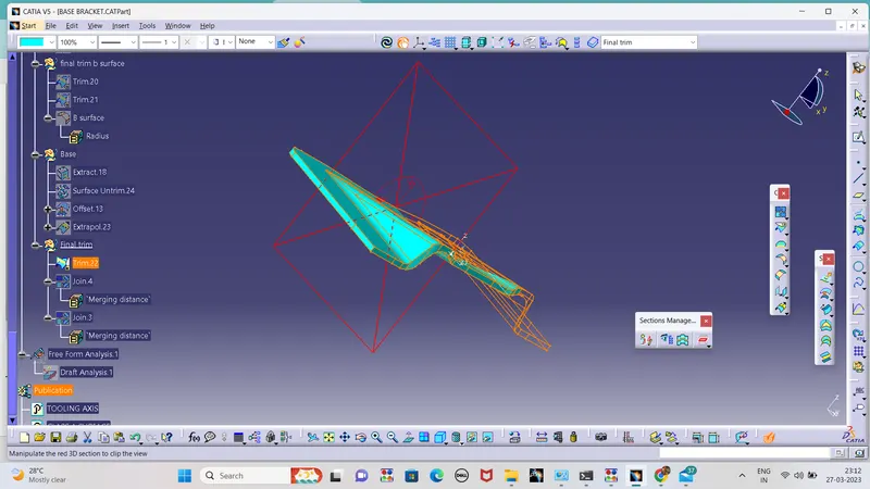
The created c surface is checked by using dynamic sectioning
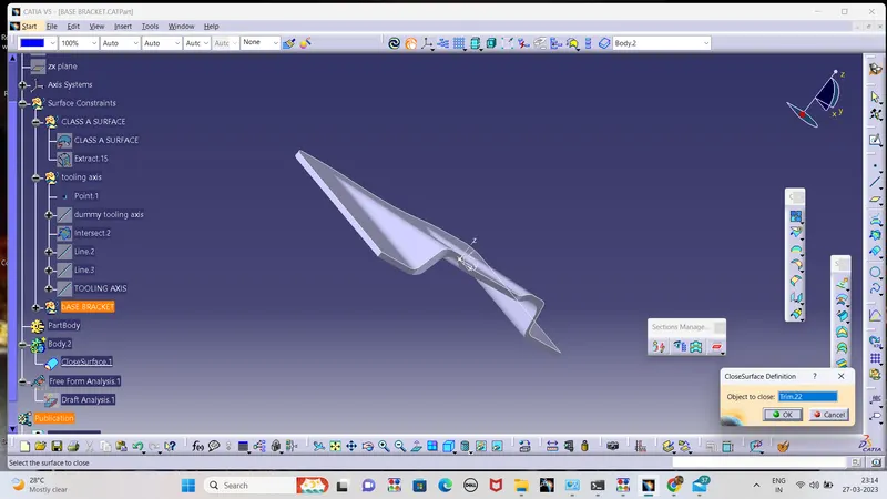
PART BODY OPERATION
Thed surface is converted is converted a part body using closed surface method
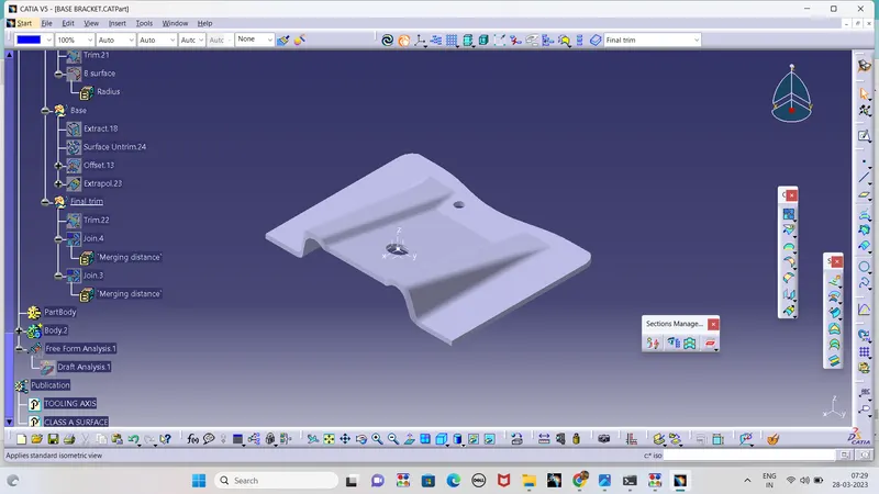
PART ORIENTATION
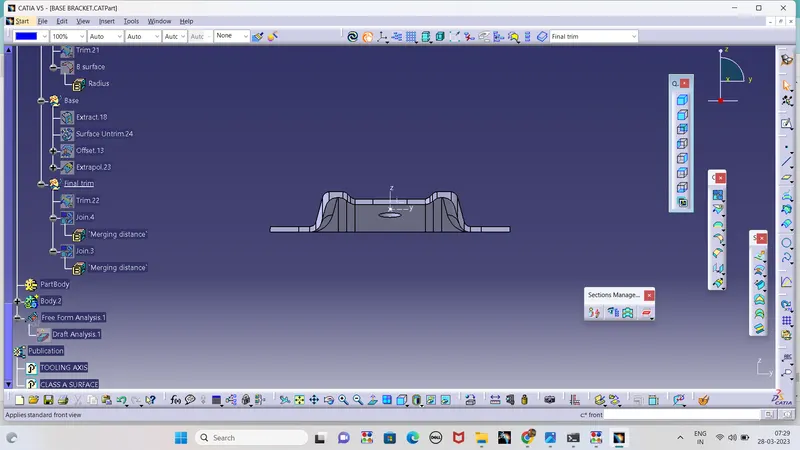
- Isometric view
- Front View
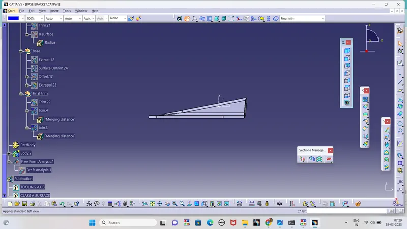
- Side View
- Top View

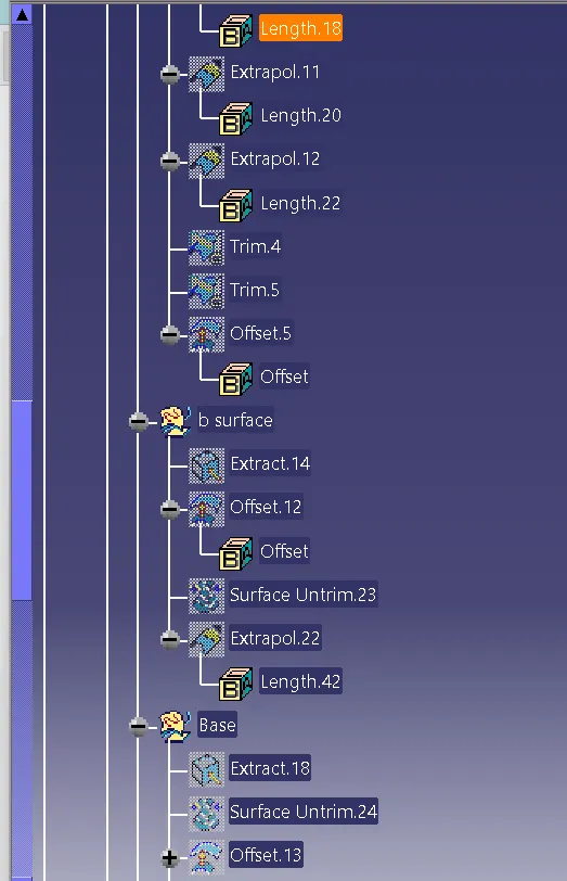
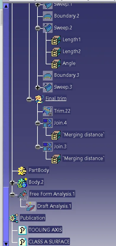
TREE STRUCTURE
CONCLUSION
Thus the Base bracket component iks created by using the given input and the required files and images are attached