Week 9 - Challenge 2 - Switch Bezel Design
AIM :
Create the Switch Bezel Plastic component through the given Class-A surface. To begin with, the tooling axis for the given Class-A Surface should be created meeting the requirements of the draft angle and at the end perform the Draft analysis on the model.
Detailed report :
Method Followed :
- Creating tool axis .
- Creating Class B surface from given Class A surface.
- Creating Class C surface from Class A & B surface .
- Creating a solid body by using a closed surface.
- Performing a draft analysis.
- Creating tool axis :
- To create the tooling axis, we need the proper orientation or view that gives the correct features and draft available in the component.
- So here the component view from the Z direction gives the proper view for the tool to see the features present in the geometry.
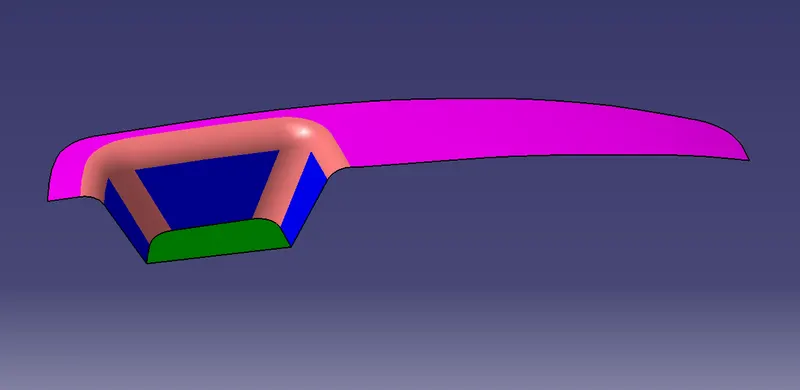
Tooling axis created by following steps :
Extracted the base surface.
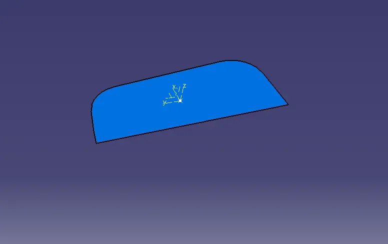
Center point is created by using the on surface at zero.
On that point the axis system is created.
Take an intersection on the YZ plane to get a boundary line.
Made a dummy axis line to form a tooling axis by a bisecting two lines.
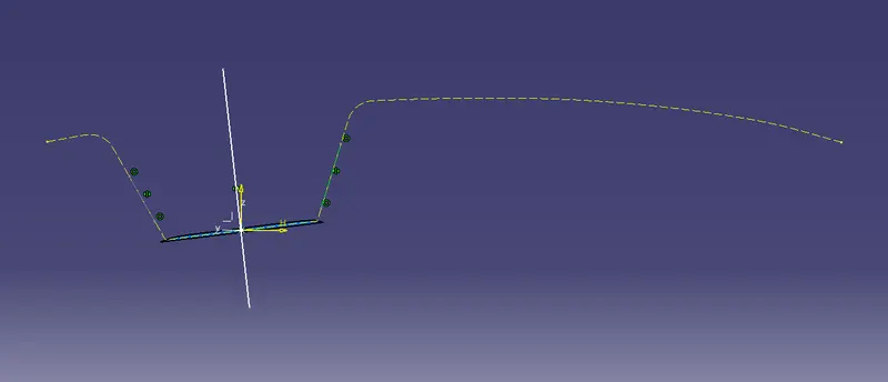
After that, switched the surface and made a sketch on the XZ plane.