Week 9 - Challenge 2 - Switch Bezel Design
Week 9 - Challenge 2 - Switch Bezel Design
Switch Bezel Surface Design :-
It is given that Create the Switch Bezel Plastic component through the given Class-A surface. To begin with, the tooling axis for the given Class-A Surface should be created meeting the requirements of the draft angle and at the end perform the Draft analysis on the model.Take the Thickness of the component to be 2.5 mm ?
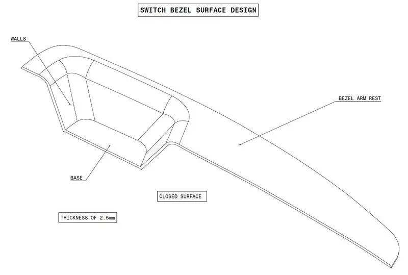
Creating Closed surface of given Class A surface Start to create tooling axis but while making axis for this part the narrow pocket the draft angle should be given degree 6.Note:- (For plastic components we provide a draft angle of 3 degree.But for Automotive Sheet Metal Parts,It will be from 7 Degree or more.)
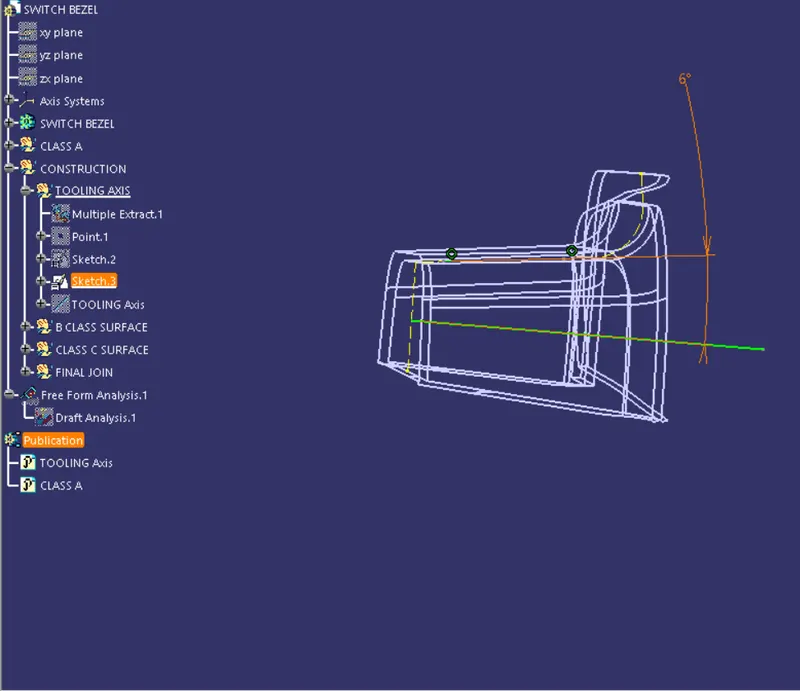
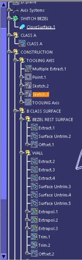
Created Tooling axis using Bisecting Line command with support of side wall project 3D command .
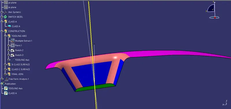
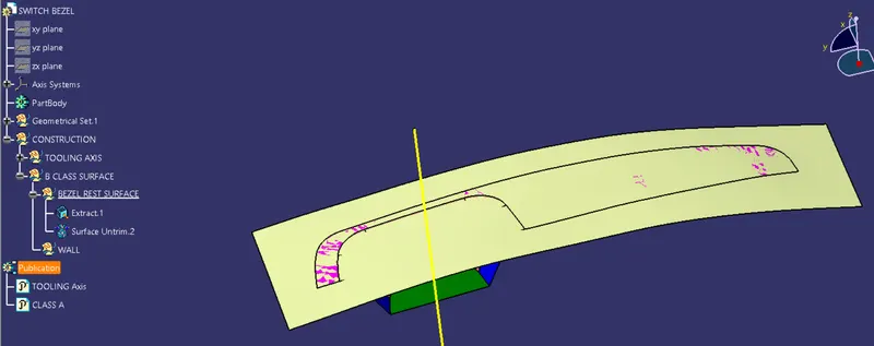
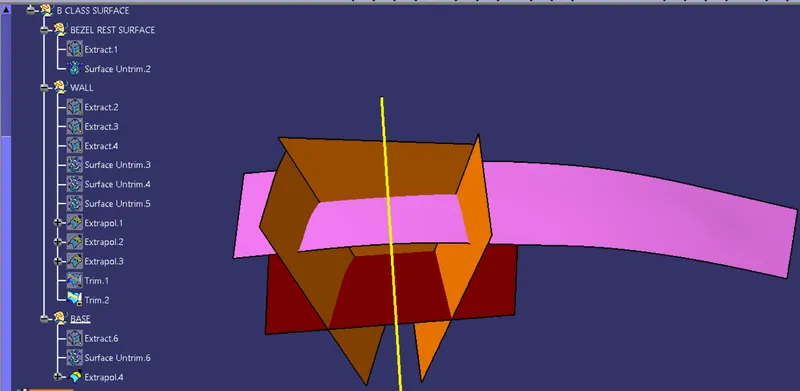
Creating B Class Surface using Extract.Selected part Switch Bezel Arm Rest Top Side.
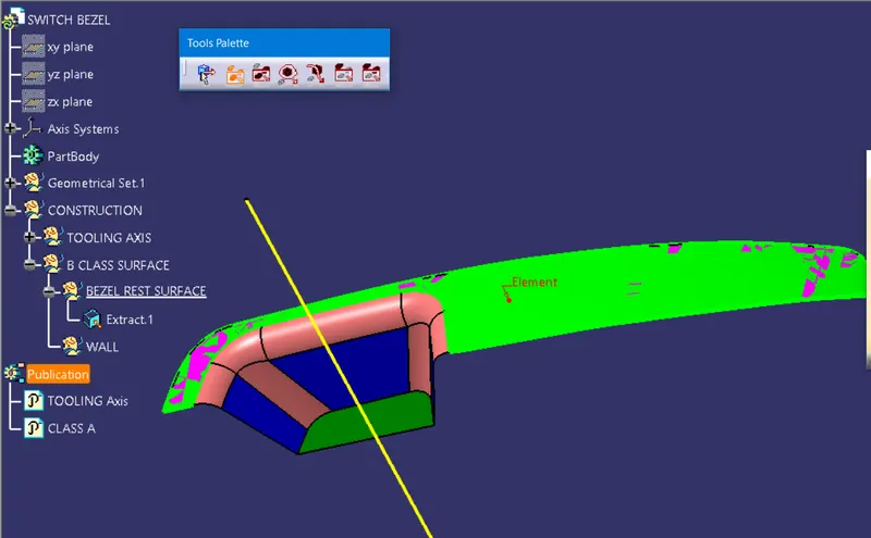
Extracted top side And Untrim the remaining Surface.
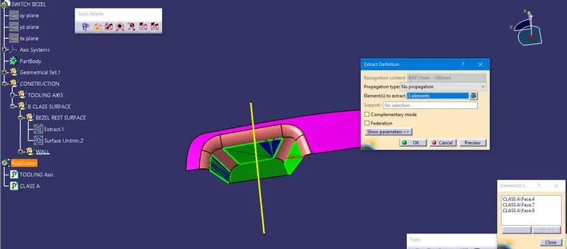
Extract Side wall Select 3 Sides of Pocket.
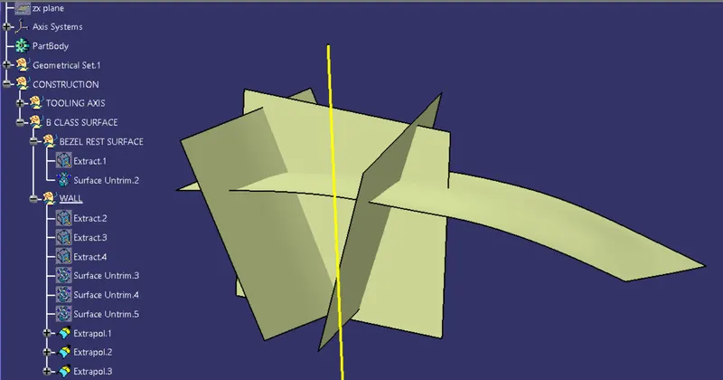
Trim and Extrapolate the untrim parts of Switch Bezel
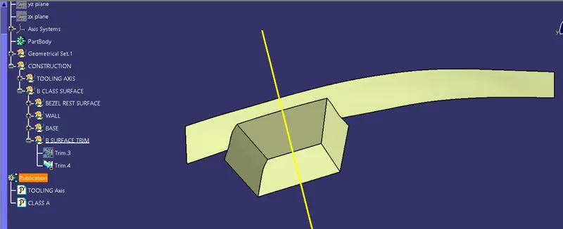
Final Trim to get required thickness.
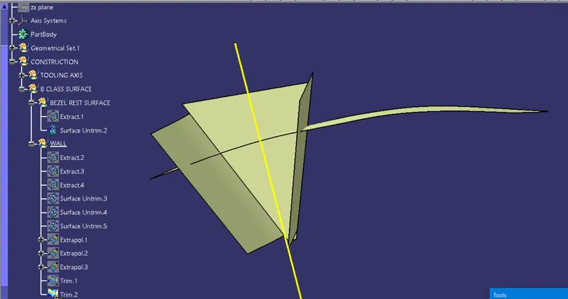
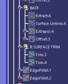
Created the remaining sides and base.Although get to next final B surface final Trim.
B surface Trim.
Check for The B class surface with A class Surface diemensions for any edge fillet present.
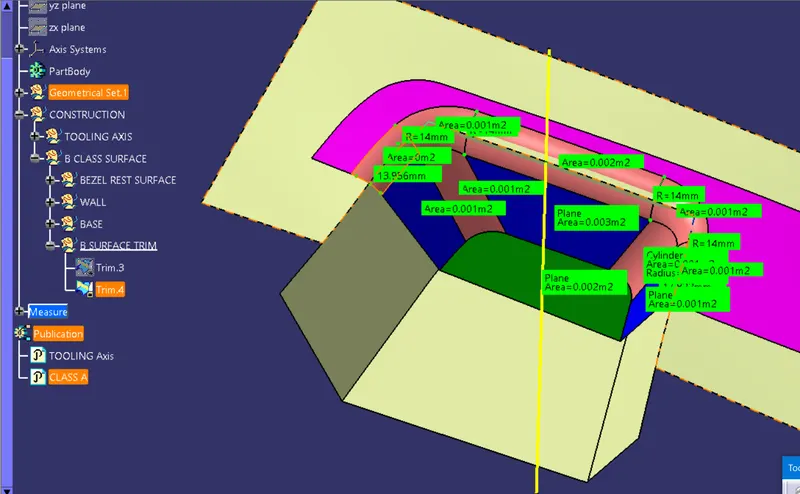
After measuring the A class edges the radius value we got was r = 14 but as we have thickness value given 2.5mm , when we give offset to sides of 2.5 the a Class radius will not fit as it is on B Class so we have to lessen the radius value 14 - 2.5 = 11.5mm to the edge fillet.
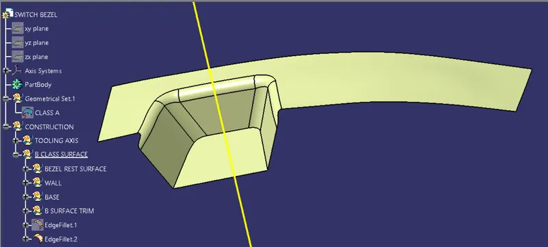
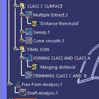
For Class C first we have to get boundary So extract A class then you will get the edge curvature on the A class avoid the extracts in multiple side it creates gaps in the while using sweep command it will increase the steps like extract,untrim and extrapolate.
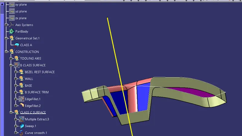
Even if you use this steps Point Continuity will creature patchs.Use next command Curve smooth it will minimize patchs.
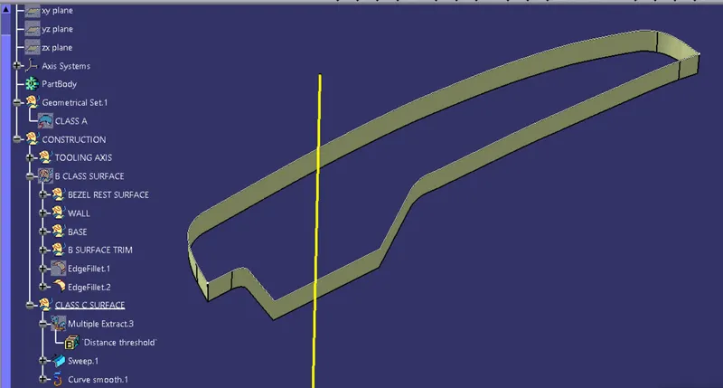
Make show all the Class A,B and C on view.
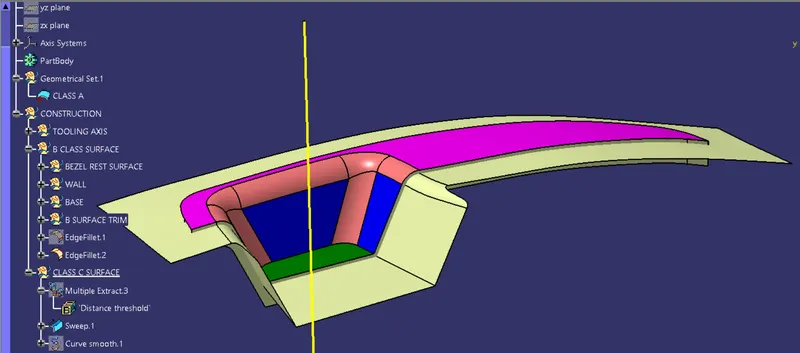
First Join Class A and Class C .
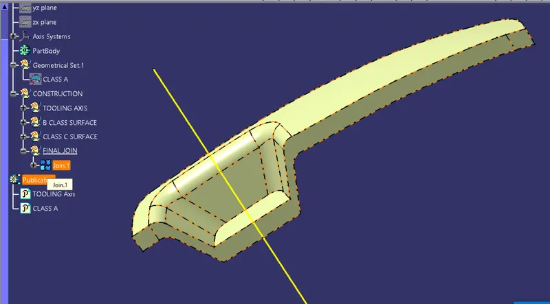
For Class C finally trim Class C and Class B .
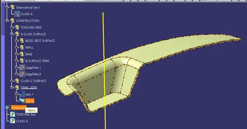
After getting Class C to solid the surface go to part Drawing select Closed Surface.
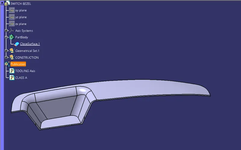
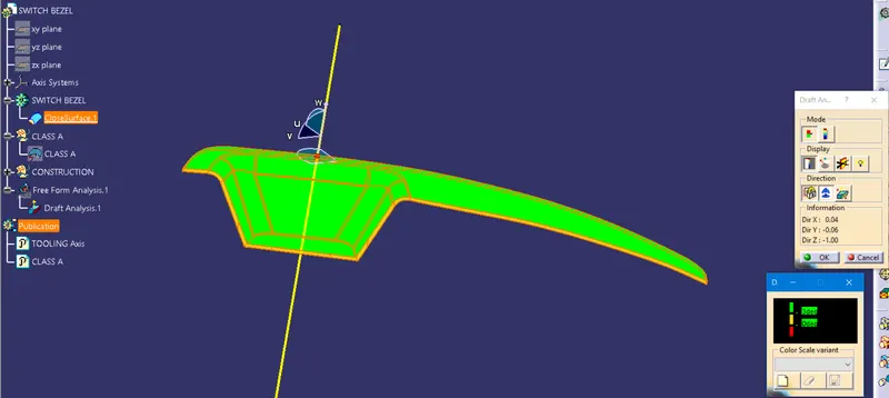
After making Solid Surface Model Now get to Draft Analysis,For Draft analysis change view mode select material call Compass on tooling axis select surface of part.It will turn green as per color scale and if changes color then that color shows certain area degree not up to the scale.in this Draft analysis their was error while the draft angle was 3 degree the middle side shows the red color because the degree that we got is 2.223 degree so after changing it to 6 degree now its above 3 degree hence it shows Green.hence Now its Procedable for further Procedure.