Week 9 - Challenge 2 - Switch Bezel Design
DRAFT ANALYSIS :
The draft analysis technique is used to analyze whether our part model created in CAD is manufacturable based on the draft condition applied. Here the part should get easily removed from the panel dies (in case of Sheet metal part) or Mold (in case of plastic).
No parts can be ejected from the tool if it is having a straight 90-degree profile from its base surface. A small draft angle is provided to each and every area of the component in order to get easy removal of the component from the tool.
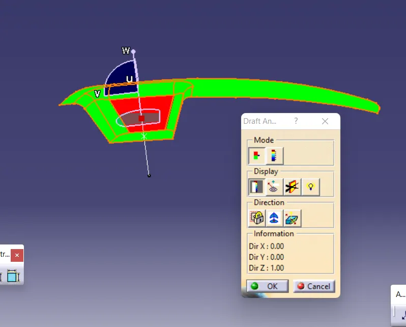
DRAFT ANALYSIS OF GIVEN CLASS A SURFACE :
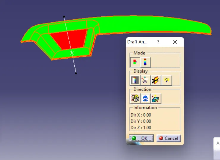
DRAFT ANALYSIS OF THE FINAL COMPONENT :
TOOLING AXIS :
The component shuod be designed under the tooling axis. We need to check visually which direction is better for tooling axis for manufacturing purpouse
First we need to creat dummy tooling axis on YZ plane. For dummi tooling, we need to create positioned sketch, in sketch we have to create to lines by using intersection line on YZ plane
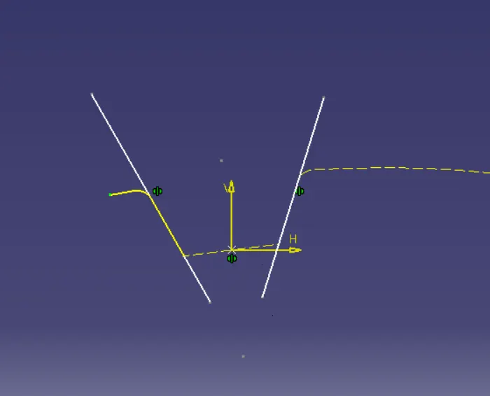
After that, we have to create the center line between these two lines by using bisecting line command .
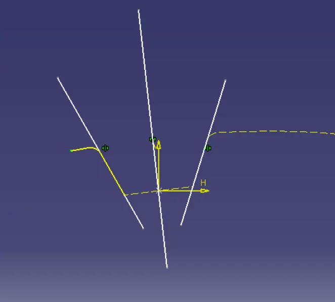
Therefore the first dummy tooling have been created . After that we have to create another dummy tooling axis on XZ plane by following the same proces of first dummy tooling axis.
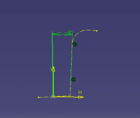
By using these two dummy tooling axises we have to create the final tooling axis line by using the command of biseciong line.
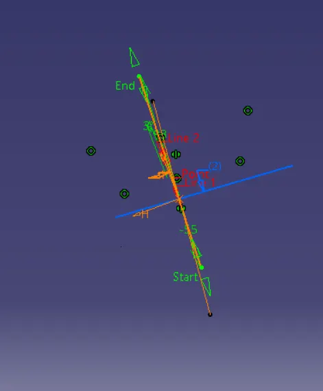
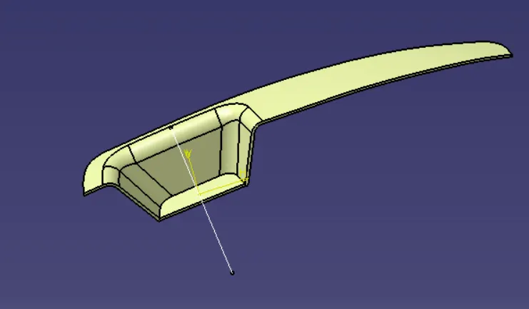
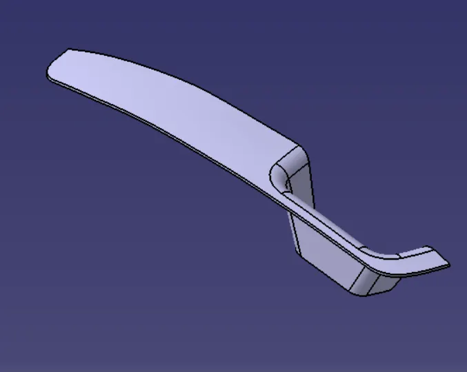
ISOMETRIC VIEW :
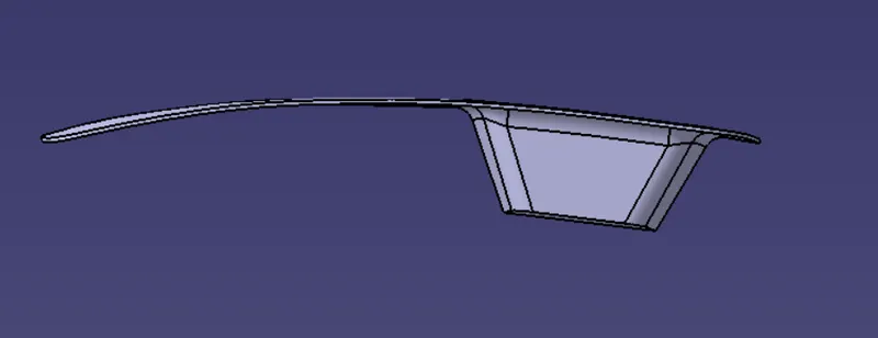
FONT VIEW :
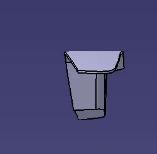
SIDE VIEW :
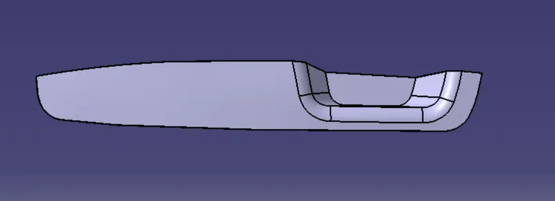
TOP VIEW :
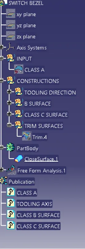
TREE STRUCTURE :