Week 9 Challenge
Question:1
In a river of linear waterway 90 m and design discharge as 700 cumec and having silt factor as 1.
Fix the span and type of foundation if HFL is 3 m from the ground.
Velocity of water 1.2m/sec
Calculate the forces as per IRC 6 on the foundation and propose the foundation.
<!-- [if !supportLists]-->1. <!--[endif]-->For Simply Supported Supported Bridge
<!-- [if !supportLists]-->2. <!--[endif]-->Continues Bridge
<!-- [if !supportLists]-->1. <!--[endif]-->Given Data
Design Discharge Q = 700 cumec
Linear Waterway = 90 m
Silt Factor = 1
Height Flood Level = 96.5 m
FRL = 100 m
GL = 93.5 m
Velocity = 1.2 m/s
Dia of Pile D = 1.2 m
Vertical Capacity = 350 t
Horizontal Capacity = 35 t
Dia of Well D1 = 6 m
Well Capacity = 50 t/m2
Dia of Well D2 = 7
Well Capacity = 60 t/m2
<!-- [if !supportLists]-->2. <!--[endif]-->Scour Depth Calculation:
Linear Waterway = 90 m
Span Arrangement (Considering)3x30m = 30 m
No of Span = 3 Nos
Height Flood Level HFL = 96.5 m
Natural Ground Level NGL = 93.5 m
Design Discharge Q = 700 cumec
Designed Discharge
as per IRC78-2014, Cl.703.1.1 Increase 30%
= 910 cumec
<!-- [if gte vml 1]>
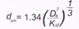
Discharge per m width (Db) = 10.11 cumec
Silt Factor (IRC:78-2014, Cl.703.2.2.1) = 1

Mean Depth of Scour(dsm) = 6.17 m
(IRC:78-2014, Cl.703.2.)
<!-- [if !supportLists]-->3. <!--[endif]-->For Abutment: (IRC:78-2014, Cl.703.2.)
Max. Depth of Scour for design of Foundation = 1.27dsm
(IRC:78-2014, Cl.703.3.1.1) = 7.69 m
Grip Length (1/3 of max. Scour depth) = 2.56 m
(IRC:78-2014, Cl.705.3.1)
Maximum Scour Level for Abutment MSL = 88.81 m
Depth of Foundation from NGL NGL-MSL = 4.69 m
<!-- [if !supportLists]-->4. <!--[endif]-->For Pier
Max. Depth of Scour for design of Foundation = 2.0dsm
(IRC:78-2014, Cl.703.3.1.1) = 12.34 m
Grip Length (1/3 of max. Scour depth) = 4.11 m
(IRC:78-2014, Cl.705.3.1)
Maximum Scour Level for Abutment MSL = 84.16 m
Depth of Foundation from NGL NGL-MSL = 9.34 m
<!-- [if !supportLists]-->5. <!--[endif]-->Level Details:
FRL = 100 m
GL = 93.5 m
HFL = 96.5 m
Pile/Well Cap Top Level from GL NGL+0.5 = 93 m
Maximum Scour Level for Abutment MSL = 88.81 m
Depth of Girder = 2.7 m
Pedestal Depth Min = 0.25 m
Thickness of Bearing Assume = 0.08 m
Depth of foundation Abutment shaft = 4.69 m
Depth of foundation Pier Shaft = 9.34 m
Abutment /Pier Top Level = 96.97 m
Height of Abutment shaft = 3.97 m
Height of foundation Pier Shaft = 3.97 m
Question:2
All the loads acting on the abutment as per IRC 6 needs to be determined for a
single span:
1 Dead Load = 572.1425t
1.1 For superstructure
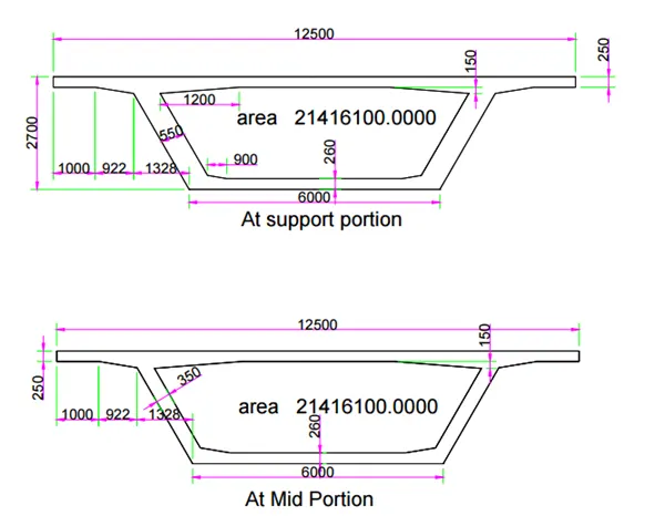
At Support portion:
Length of Girder: each segment = 10 m
No of Segment = 2
Area from Autocad = 7.96 m2
Volume = 159.196 m3
Unit weight of concrete = 2.5 t/m3
Weight of Superstructure = 397.99 t
At Mid portion:
Length of Girder: each segment = 10 m
No of Segment = 1
Area from Autocad = 6.97 m2
Volume = 69.661 m3
Unit weight of concrete = 2.5 t/m3
Weight of Superstructure = 174.1525t
Total Weight of superstructure = 572.1425t
<!-- [if !supportLists]-->· <!--[endif]-->Superstructure figure:
1.2 For Sub-Structure = 210.4 t
1.2.1 Abutment Cap Rectangular Portion Length = 12.5 m
Wdth = 2.52 m
Height = 0.5 m
Volume = 15.75 m3
Unit weight of concrete = 2.5 t/m3
Weight of sub-Structure = 39.375 t
Trepezoidal Portion Length = 12.5 m
Wdth = 2.01 m
Height = 0.5 m
Volume = 12.5625 m3
Unit weight of concrete = 2.5 t/m3
Weight of sub-Structure = 31.40625t
Total Weight of Abutment Cap = 70.78125t
1.2.2 Abutment wall/Shaft Top Level of Abutment Cap = 96.97 m
Bottom Level of Abutment Cap = 95.97 m
Ground Level = 93.5 m
Foundation top below GL Min. = 0.5 m
Length = 12.5 m
Width = 1.5 m
Height = 2.97 m
Volume = 55.6875 m3
Unit weight of concrete = 2.5 t/m3
Weight of Wall/shaft = 139.21875t
1.2.3 Pedestal
Length = 0.8 m
Width = 0.8 m
Height min. 250mm = 0.25 m
Volume = 0.16 m3
Unit weight of concrete = 2.5 t/m3
Weight of pedestal = 0.4 t
Total Weight of sub-Structure = 210.4 t
2 Super-Imposed Dead Load
2.1. Wearing Coat
Unit Weight = 2 t/m3
Length = 30 m
Width = 12.5 m
Thickness = 0.065 m
Volume = 24.375 m3
Weight in Tonne = 48.75 t
2.2 Crash Berrier
Unit Weight = 1 t/m3
No of Side = 2
Length = 30 m
Width = 1 m
Area = 1 m
Volume = 60 m3
Weight in Tonne = 60 t
2.3 Dirtwall
Unit Weight = 2.5 t/m3
Length = 12.5 m
Width = 0.3 m
Height FRL-Cap Top Level = 3.03 m
Volume = 11.3625 m3
Weight in Tonne = 28.40625t
3 Live load 70R wheel = 100 t
Loads Summary on Abutment Dead Load Super 572.1425/2 = 286.07 t
Sub = 210.40
Crash Berrier 60/2 = 30.00 t
Wearing Coat 48.75/2 = 24.38 t
Dirtwall 28.40625 = 28.41 t
Live load 100/2 = 50.00 t
Total Load acting on Abutment cap excluding earth pressure, braking Live load Surcharge, frictional force of bearing = 629.25 t
Loads Summary on Pier(Both Span Loaded)
Dead Load Super = 572.14 t
Sub = 210.40 t
Crash Berrier = 60.00 t
Wearing Coat = 48.75 t
Dirt wall = 28.41 t
Live load = 100.00 t
Total Load acting on pier excluding braking frictional force of bearing = 1,019.70 t
For Seismic case, Load increase 25% of total acting load = 1,274.62 t
Question:3
What is zero shear point and if there is more scour at region what will be the effect of that on zero shear point.
Answer:
Zero Shear Point:
The points other than the extreme ends of a beam in a beam at which bending moment is zero are called Points of contraflexure or inflexion.
The point at which we get zero share force we get the maximum bending moment of that section at that point.
In the context of soil mechanics and geotechnical engineering, the term "zero shear point" refers to a specific point on the stress path of a soil sample undergoing shear testing, such as a triaxial shear test or a direct shear test. It is a point on the stress-strain curve where the shear stress is zero.
At this point, the soil is no longer resisting shear deformation, and it has reached a state of no shear strength.
The effect of scour on the zero-shear point and soil behaviour depends on the specific context and how the soil samples are affected:
<!-- [if !supportLists]-->· <!--[endif]-->Shear Strength Reduction:
Scour can lead to a reduction in the effective stress and, consequently, a reduction in the shear strength of the soil. The zero-shear point may be affected by this reduction, potentially shifting along the stress-strain curve. In some cases, it may even result in negative effective stress, indicating that the soil is in a state of tension rather than compression.
<!-- [if !supportLists]-->· <!--[endif]-->Changes in Soil Properties:
Scouring can alter the properties of the soil in the scoured region. The soil's grain size distribution, density, and cohesion may change, all of which can affect its shear strength and behaviour under shear loading. This, in turn, can influence the location of the zero-shear point.
<!-- [if !supportLists]-->· <!--[endif]-->Stability Concerns:
Excessive scour can lead to instability of structures built on or in contact with the soil, such as foundations, retaining walls, or bridge piers. The reduction in shear strength and changes in soil properties may result in reduced load-bearing capacity and increased risk of failure.
<!-- [if !supportLists]-->· <!--[endif]-->Monitoring and Mitigation:
Engineers and geologists often monitor and assess the extent of scour in critical areas to ensure the safety and stability of structures. Mitigation measures, such as adding additional support or protective measures, may be taken to address the effects of scour on the soil and structures.
In summary, the zero-shear point represents a specific point on the stress-strain curve during shear testing, indicating the point at which the soil's shear stress is zero. When scour occurs in a region, it can have various effects on the zero-shear point and soil behaviour, including reductions in shear strength and changes in soil properties. Engineers and geologists must consider these effects when assessing the stability and safety of structures in areas prone to scour.
Question:4
Define the Liquefaction and its effects, how it can affect foundation. Also list the remedial measures for the same. How it is different from scouring?
Answer: -
Liquefaction is a geotechnical phenomenon that occurs when saturated granular soils, such as sand and silt, temporarily lose their strength and stiffness due to an increase in pore water pressure.
This typically happens during seismic events, but it can also occur during other types of rapid loading, such as from heavy rainfall or construction activities.
Liquefaction can have significant adverse effects on structures and foundations built on or in these soils.
Here's a breakdown of liquefaction:
<!-- [if !supportLists]-->· <!--[endif]-->Its effects
<!-- [if !supportLists]-->· <!--[endif]-->Its impact on foundations and
<!-- [if !supportLists]-->· <!--[endif]-->Remedial measures:
<!-- [if !supportLists]-->· <!--[endif]-->Effects of Liquefaction:
Loss of Bearing Capacity:
Liquefaction reduces the ability of the soil to support the weight of structures, leading to settlement or even structural failure.
Ground Shaking:
Liquefied soils can amplify ground shaking during an earthquake, which can further damage structures.
Tilt and Differential Settlement:
It can cause differential settlement, leading to tilting and cracking of buildings and infrastructure.
Uplift of Foundations:
In some cases, liquefaction can cause foundations to "float" upward due to buoyancy forces created by the liquefied soil.
<!-- [if !supportLists]-->· <!--[endif]-->Impact on Foundations:
Liquefaction can adversely affect foundations in several ways:
<!-- [if !supportLists]-->1. <!--[endif]-->Foundations may settle unevenly, causing structural damage.
<!-- [if !supportLists]-->2. <!--[endif]-->Piles and deep foundations may lose support as the surrounding soil liquefies.
<!-- [if !supportLists]-->3. <!--[endif]-->Uplift pressure can damage shallow foundations.
<!-- [if !supportLists]-->4. <!--[endif]-->Tilted or damaged foundations can lead to structural instability.
<!-- [if !supportLists]-->· <!--[endif]-->Remedial Measures for Liquefaction:
<!-- [if !supportLists]-->1. <!--[endif]-->Improving Soil Properties:
One approach is to densify or improve the soil by methods like compaction, dynamic compaction, or vibro-compaction.
<!-- [if !supportLists]-->2. <!--[endif]-->Use of Piles:
Installing deep foundations like piles can transfer loads to stable soil or bedrock below the liquefied layer.
<!-- [if !supportLists]-->3. <!--[endif]-->Ground Improvement Techniques:
Methods like soil grouting, stone columns, or soil mixing can be used to increase soil strength and reduce liquefaction potential.
<!-- [if !supportLists]-->4. <!--[endif]-->Base Isolation:
For critical structures, base isolation systems can be used to decouple the structure from ground motion during earthquakes.
<!-- [if !supportLists]-->5. <!--[endif]-->Lateral Reinforcement:
Reinforcing retaining walls and other structural elements to resist lateral loads from liquefaction.
<!-- [if !supportLists]-->· <!--[endif]-->Difference from Scouring:
Liquefaction and scouring are two different geotechnical phenomena:
<!-- [if !supportLists]-->1. <!--[endif]-->Liquefaction:
As described above, liquefaction involves the temporary loss of strength in saturated granular soils, typically due to seismic or rapid loading conditions.
<!-- [if !supportLists]-->2. <!--[endif]-->Scouring:
Scouring is the erosion or removal of soil or sediment from around the base of a structure, such as a bridge or a foundation, usually caused by the flow of water. It can occur due to natural factors like river currents or man-made factors like excessive water flow from rainfall or dam releases.
In summary, liquefaction involves the temporary weakening of soil due to changes in pore water pressure, often caused by seismic events, while scouring is the erosion of soil around a structure due to the flow of water. Both can have significant impacts on foundations, but they are distinct processes with different causes and mechanisms, requiring different mitigation measures.