Week 9 - Challenge 1 - Base Bracket Design
BASE BRACKET PLASTIC COMPONENT DESIGN
Aim :- To design the Base Bracket plastic component through the given Class-A surface.
Objective :-
- To create a proper tooling direction.
- To perform draft analysis of the plastic component.
- To design the base bracket plastic component by creating the B-Surface and C-Surface using the given Class-A surface.
Introduction :-
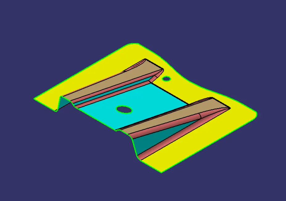
CLASS-A SURFACE : A surface made by the designer which is given as an input to the plastic modeler to work on. It is aesthetic surface and the outer most surface.
CLASS-B SURFACE : A surface below a certain thickness from the class-A surface is class-B surface. This is the surface that contains engineering aspects of a model.
CLASS-C SURFACE : A surface that joins class-A and class-B surfaces is class-C surface.
Methodology :-
In this model we have focused on the following things:-
- Tooling axis.
- Draft analysis.
- Class-B surface.
- Class-C surface.
- Making a solid model from surface.
Following tools were used to reach the final step:-
- Extract.
- Un-trim.
- Trim.
- Extrapolate.
- Offset.
- Edge fillet.
- Boundary.
- Sweep.
- Joint.
- Close Surface (part design).
Tooling Direction :-
Tooling axis is the direction in which mold or core and cavity opens. The ejection of the part from mold depends on the draft. A zero draft can result in difficult or no ejection due to shrinkage. It is recommended to add a minimum of 0.5 to 1 degree upto 3 degree of the draft for non-textured surface & 3 to 5 degree of draft for textured surfaces.
Procedure to create the tooling axis using bisecting method :-
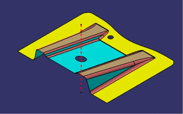
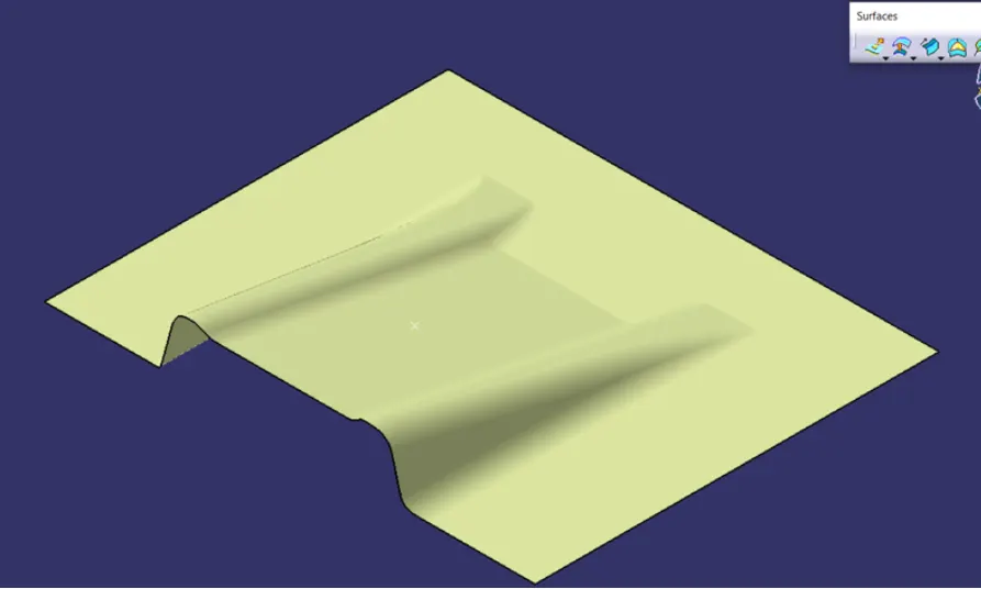
following Class A surface is provided to design the base bracket plastic component
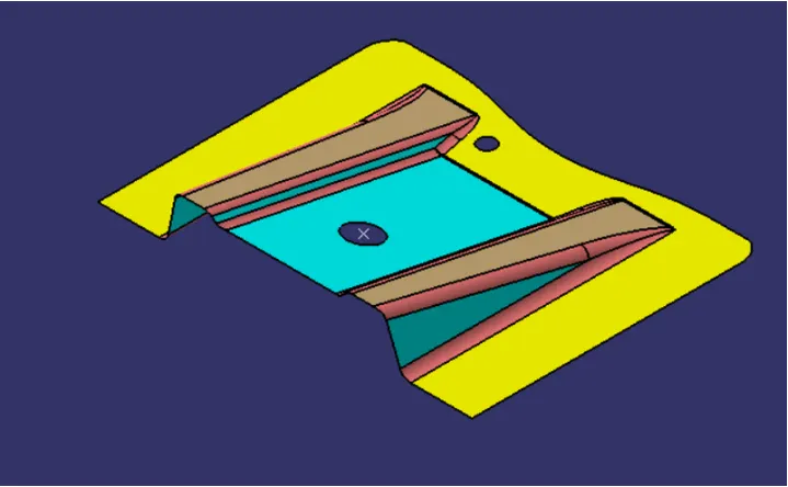
YZ Plane is created at the center of the hole and intersection of a surface is taken along the created plane.
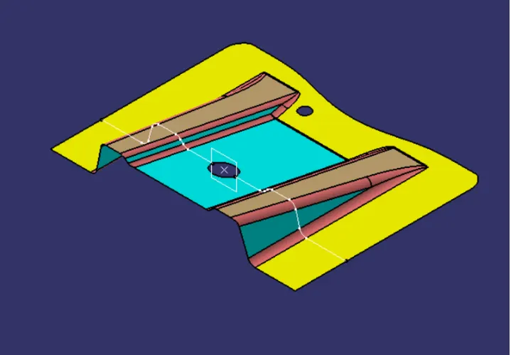
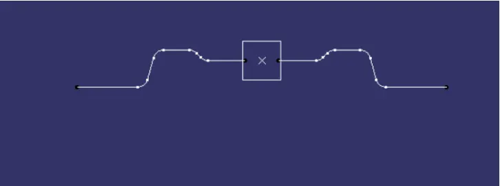
In this way we can create the tooling direction.
Draft analysis :-
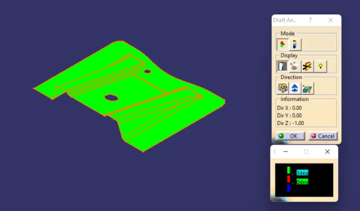
- Go to insert< analysis< feature draft analysis.
- Align the tooling axis with the compass.
- Click on the surface and see that the surface is within the permissible limit of the draft values.
- The surface should be green and in the column proper value (3deg) should be inserted.
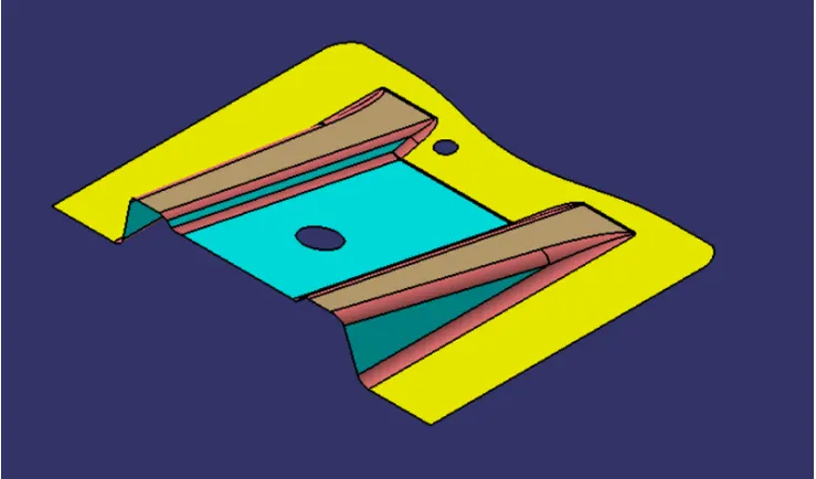
Class A-Surface :-
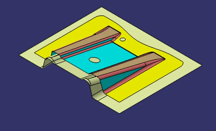
Class B-Surface :-
Class B-Surface is extracted from the A-surface and it is offseted at 2.5mm in downward direction.
Class C-Surface :-
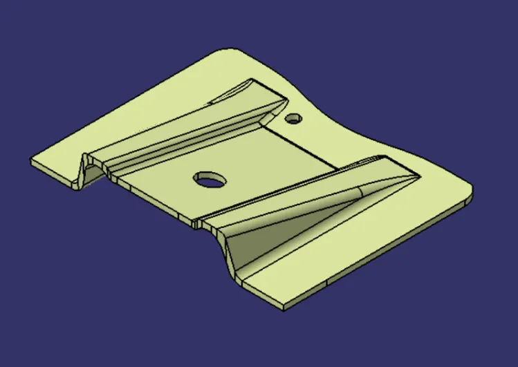
C-Surface connects the class A-Surface and B-Surface. It is created using Sweep command. Boundry of the class A-Surface is swept along the tooling direction.
Conclusion:
There fore final part has been made with the help of Class-A surface.