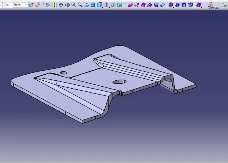
Week 9 - Challenge 1 - Base Bracket Design
AIM:-
To create the Base Bracket Plastic component through the given Class-A surface. To begin with, the tooling axis for the given Class-A Surface should be created meeting the requirements of the draft angle and at the end to perform the Draft analysis on the model. Thickness of Plastic Part should be 2.5 mm.
DESCRIPTION:-
- Geometrical sets are having a proper name based on the sketches present inside of it
- All the sketches are created under the Geometrical set
- Used the Close Surface feature to make a solid body from the surface.
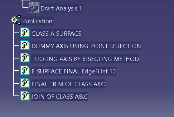
- Publications: Using the publication option and published the below
- Tooling Axis & Class A, B, and C surface.
- Screenshots of the Draft analysis report for both the given Class-A surface and the final plastic component are attached below.
- Screenshots of the solid model with the proper color code of the draft angle in various orientations (Isometric, Front, Side, and Top View) are attached below.
TOOLING AXIS:-
From the given class A surface tooling axis will be created on the basis of direction of the movement of core which has to clear all the shapes of the final part of mold or otherwise visible side of the class A with all the shape of the mold including holes. To avoid using side core Which will be cost effective so our motto is to clear all the things in main tooling axis itself.
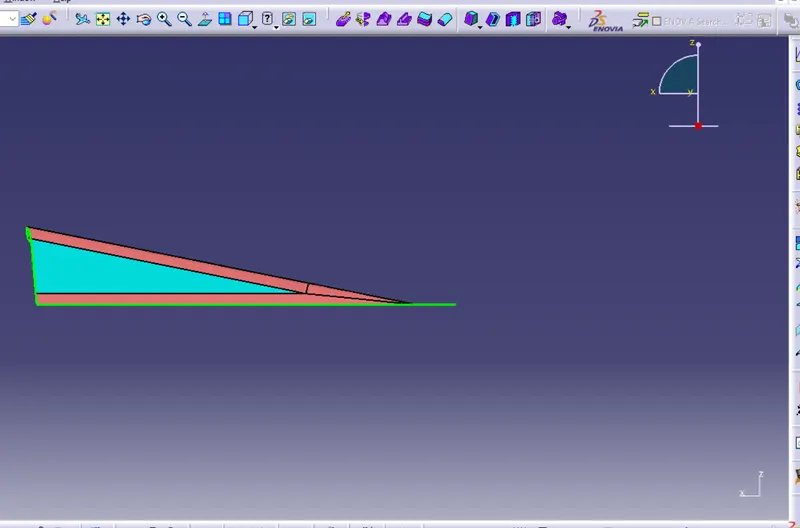
The above image shows y direction of the class A surface which is not feasible for tooling because of the holes are not visible here.
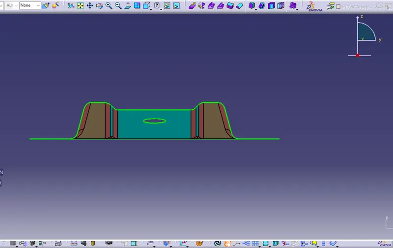
The above image is the x direction of the class A surface which is good compared to y direction but the bottom hole is missing so it is also not feasible for creating a tooling axis.
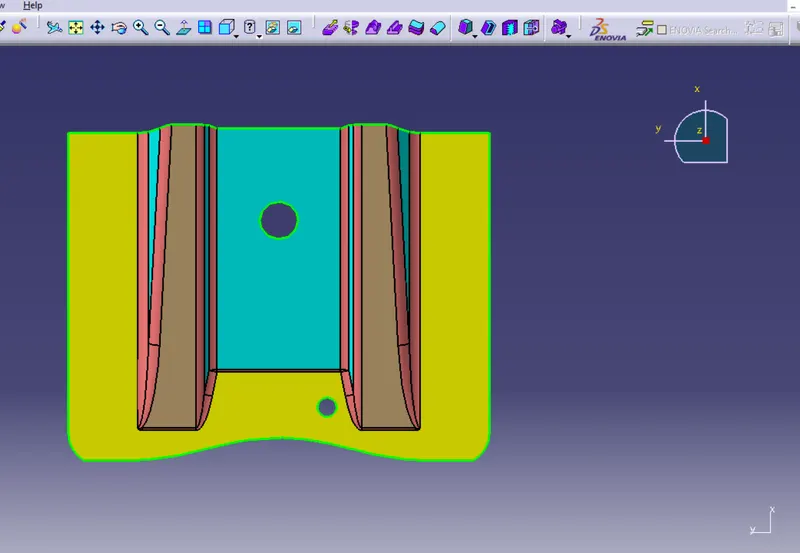
The above image is the z direction of class A surface which is clearing the two holes as well as the surface are also clearly visible for tooling. so we will choose the z direction for tooling axis.
Here we've used two methods for creating tooling axis
- Point direction method
- Bisecting method
Point direction method:-
By this method using a point to create an axis along preffered direction.
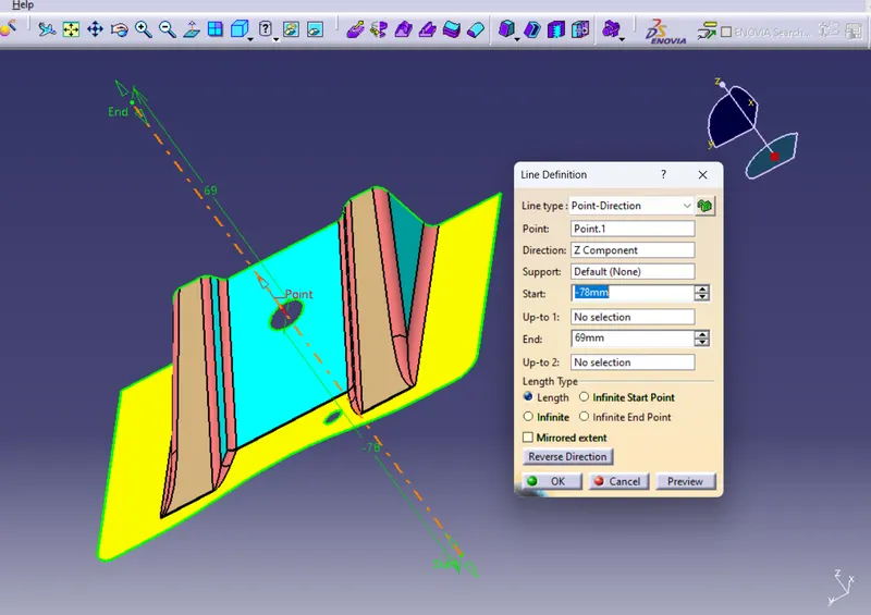
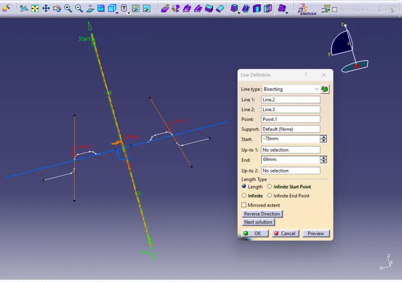
Bisecting method:-
From this method we can able to create an axis by bisecting two parallel lines along an required axis. If some class A has more curves and fillets inorder to have a perfect draft angle we will use this method to create a tooling axis which will be in centre for both the curves. This is the another type of creating tooling axis.
DRAFT ANALYSIS REPORT:-
Once the tooling axis is created draft angle to be checked along tooling axis direction.
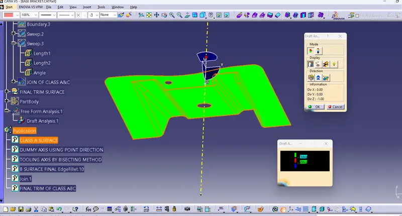
The above image shows the draft analysis for the given class A surface, a positive draft angle of 3deg is showing which means it meets the nominal value of draft and good to go for creating B&C surface. But before creating tooling axis & checking draft angle need to check the given class A surface is a closed boundary.
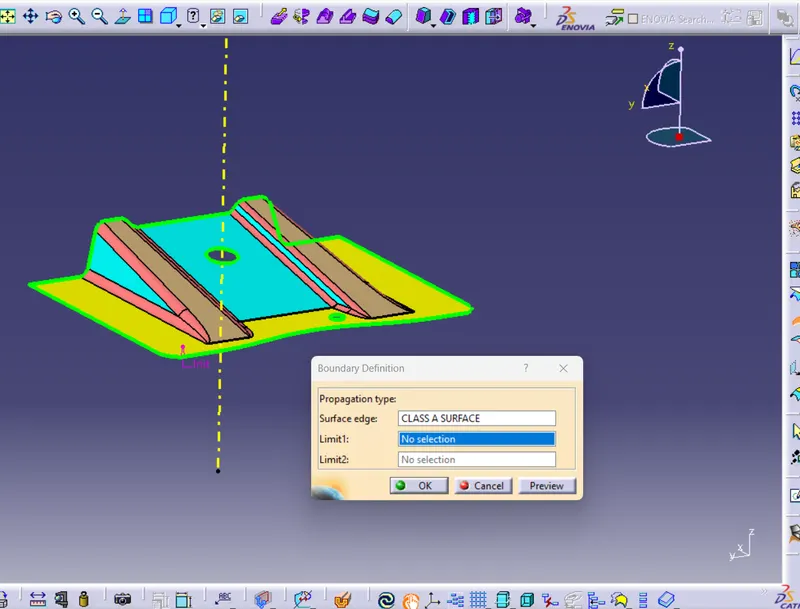
Draft analysis of the final solid part:-
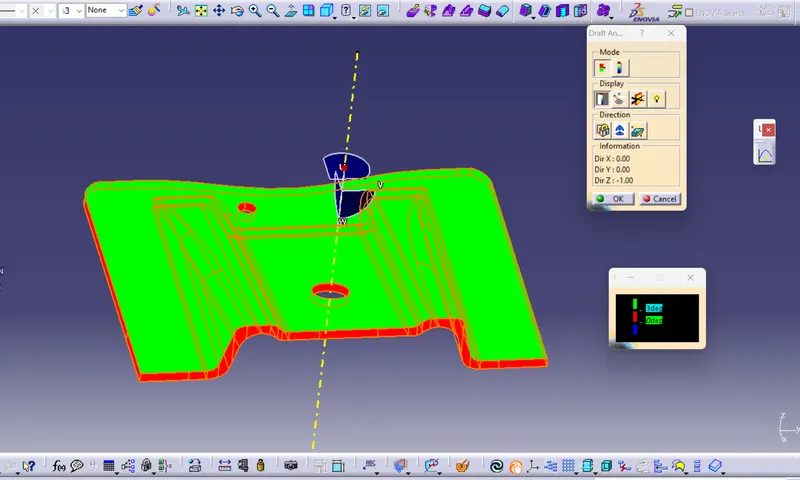
Screenshots of the solid model with the proper color code of the draft angle in various orientations (Isometric, Front, Side, and Top View):-
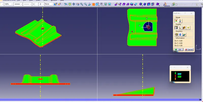
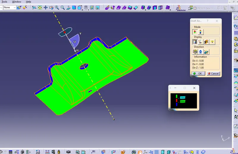
Draft analysis done for both the directions of the final solid body it shows the same positive draft angle 3deg.
Publications screenshot:-
Solid body from close surface command:-