Week 9 - Challenge 1 - Base Bracket Design
STEP 1: The connectivity of the Class A Surface was checked using the JOIN command.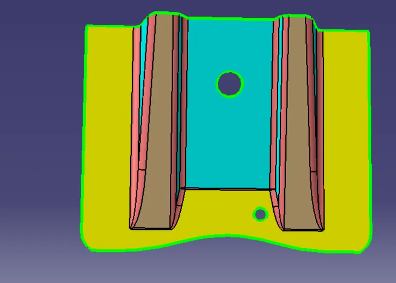
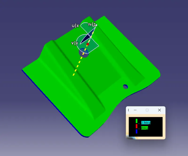
STEP 2: The tooling axis was created using the bisection of two lines. These two lines are the intersection of class A with a plane about a chosen point.
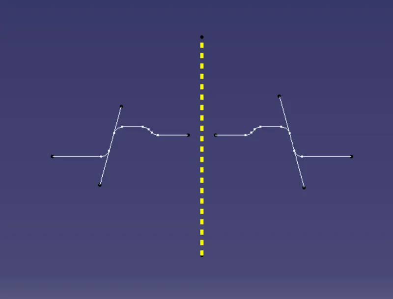
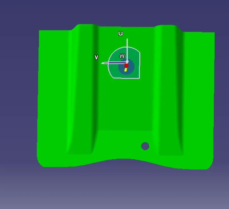
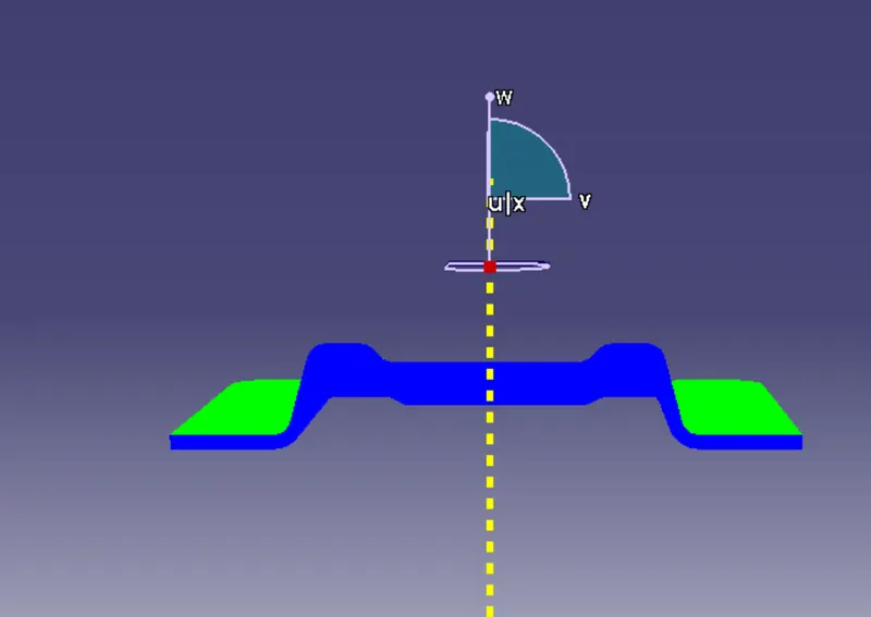
STEP 3: Draft analysis was done about the tooling axis.
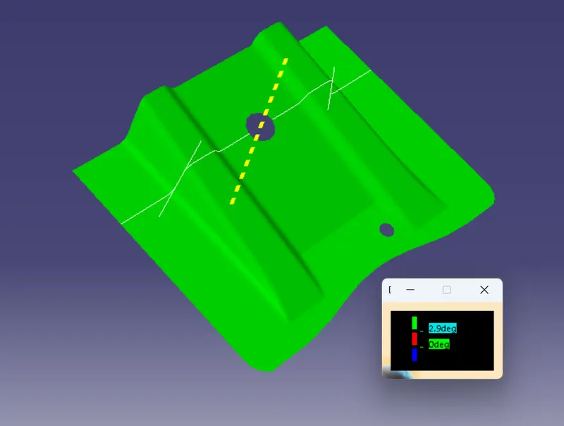
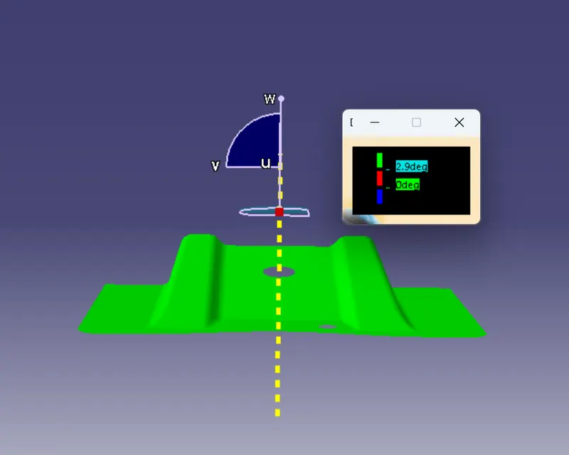
Step 4: An offset of class A was made below it by selecting individual surfaces. These surfaces went through extract, untrim, offset, and then trimmed together. This is now the class B surface.
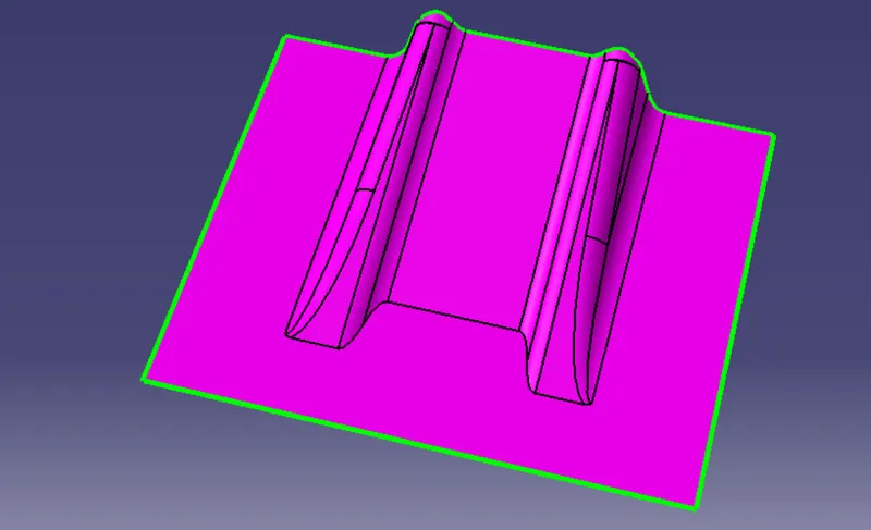
Step 5: A boundary of Class A was made and then then it was swept at 3 degrees along the draft direction using the SWEEP command and WITH DRAFT DIRECTION. This is class C.
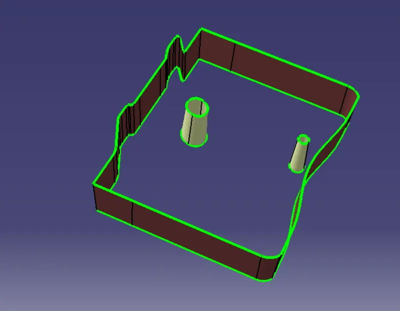
Step 6: Then Class A and Class C were joined.
Step 7: Then Class A+C was trimmed with Class B.
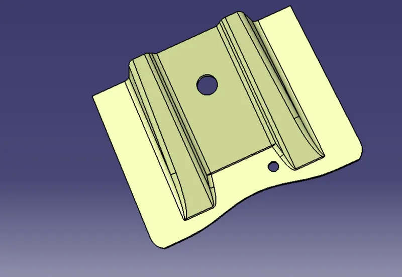
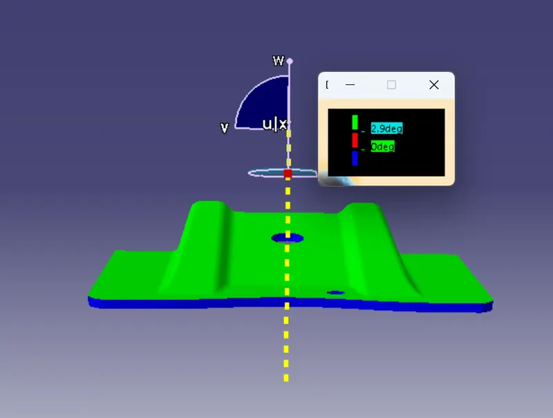
Step 8: The surface was made into a solid using the Close Surface command in the mechanical part design workbench.
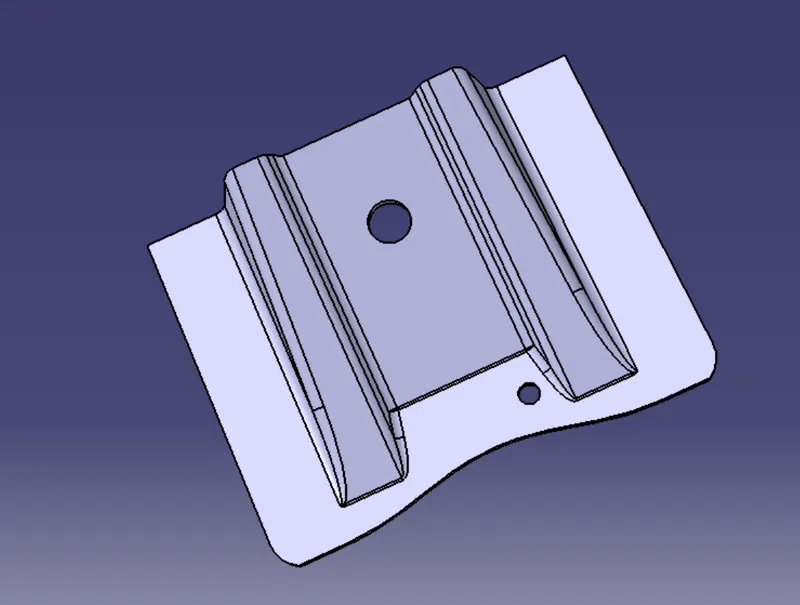
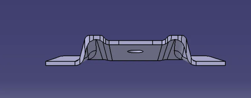
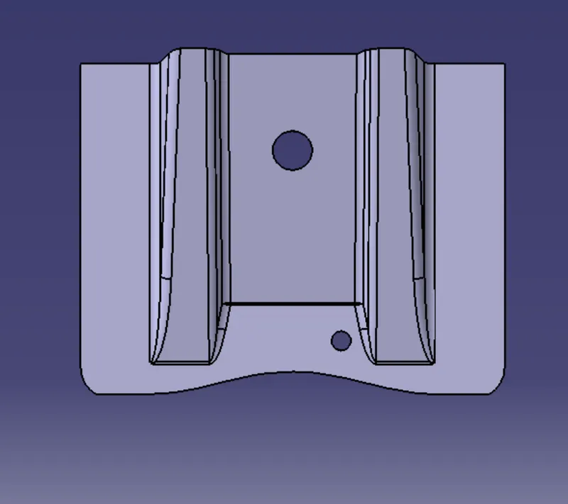
Step 9 : Again draft was analyzed.