Week 9 - Challenge 1 - Base Bracket Design
AIM:- Create the Base Bracket Plastic component through the given Class-A surface. to
begin with, the tooling axis for the given Class-A Surface should be create meeting the requirments
of the draft angle and at the end perform the Draft analysis on the mode
OBJECTIVE:-
. Creation of Tooling Axis.
. Creation of class B and C surface.
. Creating a solid part out of surface modeling.
. Draft Analysis of class A surface an final plastic component.
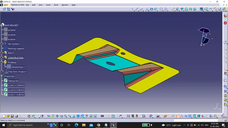
CLASS A:- Following Surface is given as the input for the component creation.
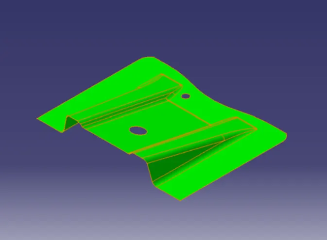
Draft Analysis for surface A:
The analysis is done for 3deg draft. So as can be seen all the surfaces are more than 3deg.
Creating of Tooling Axis:
. Create an intersection of CLASS A surface with ZX plane and from the intersection create the
tooling axis as shown below.
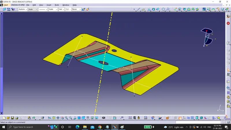
. Create a bisecting line using the lines shows above
. Lines shown in dotted green is our tooling axis
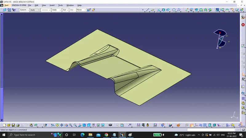
Creation of Class B Surface:
. We have to extract faces from class A surface, and untrim them to obtain original parent surface.
. This surface are then offset to the required thickness.
. Required fillets are given to the Surfaces.
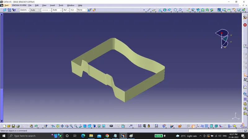
Creation of class c:
. For creating this surface we have to extracted the boundry of class A.
. Now swept along the draft direction with a 3deg draft.
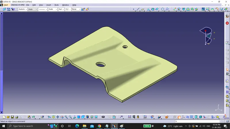
Final Trims:
Class A+Class C
To make sure that thereis not any open boundry between class A and Class c, we have used
join option to created the single body. This is done to make sure that the parting line doesnt
line between the these two surfaces.
Class A+Class B+Class C
For this we have trimmed the join of the class A and class C surfaces with the class B.
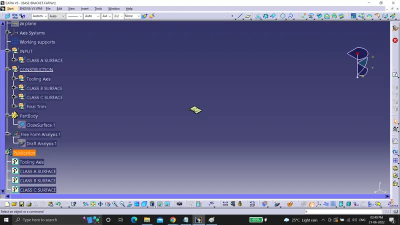
Specification Tree
Draft Analysis:
For this analysis main tooling axis in taken draft reserence,
Following results were Obtained:
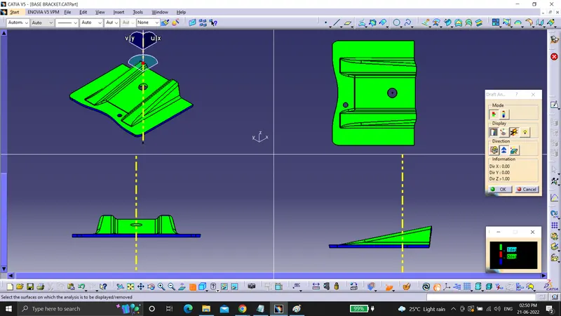
Screenshots of the solid model with proper color code of the draft angle in various
orientations (Isometric, Front, and Top View).