Week 9 - Attachment Feature Creation (Ribs & Screw Boss) - Challenge 1
RIB'S & SCREW BOSS DESIGN
Create the rib for the Door Handle considering the design rules mentioned in this challenge.
CLASS-A- SURFACE CREATIONS
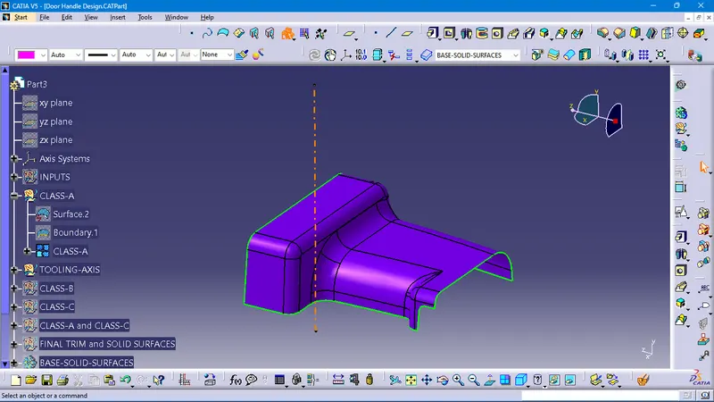
To make sure that the given surface has no gap, between them. We can check it visually and also with help of Join or boundary commands.
TOOLING AXIS CREATIONS
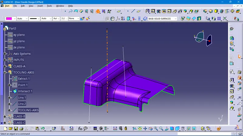
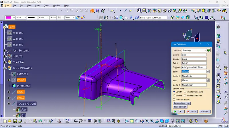
The direction in which the mold/core and cavity open. The selection of the direction of the tooling axis depends on the Case at which components can be quickly ejected. By analyzing the component the most easily ejectable direction is somewhere close to the Z direction,(might be inclined to it) so we have sketched on the YZ plane of the Axis System) to create a bisecting line considering the 2 faces which might be difficult to be tooled. The tooling axis is created by using the bisecting method line command.
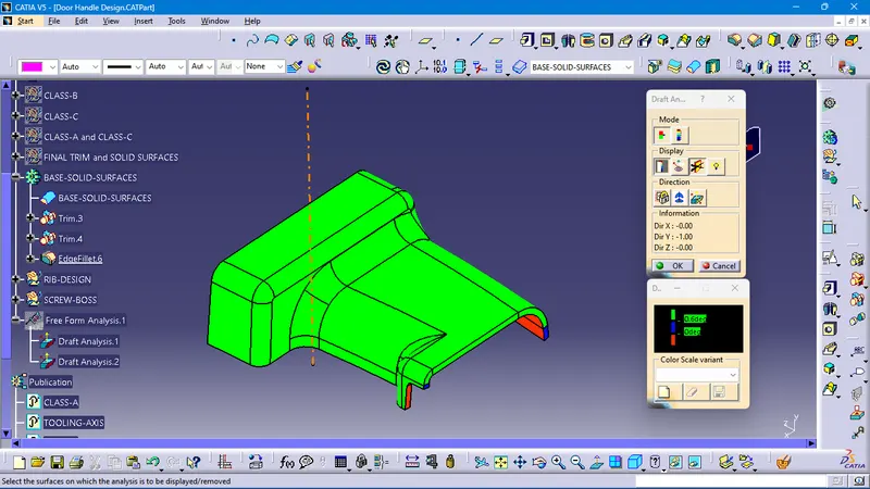
DRAFT-ANALYSIS on CLASS-A SURFACE
Change the view to the MATERIAL mode for draft analysis
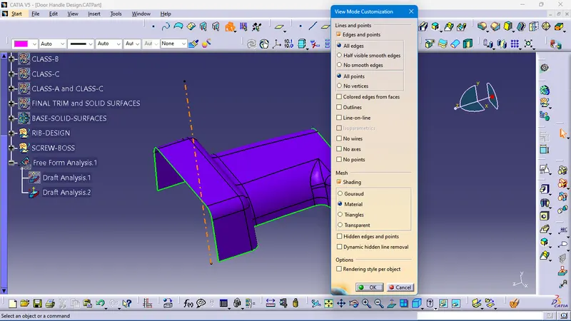
select the compass function to align the compass to the tooling direction and lock the direction using the lock function in the draft analysis toolbar
the surface is showing green color so that the surface clears the minimum draft angle of 0.5 to 3 degrees
By using the analyses under the running point we can check the draft angle on the individual faces. It shows how many drafts are on specific points when we move the cursor point.
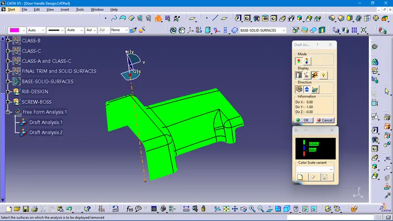
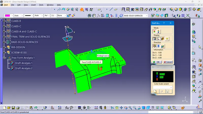
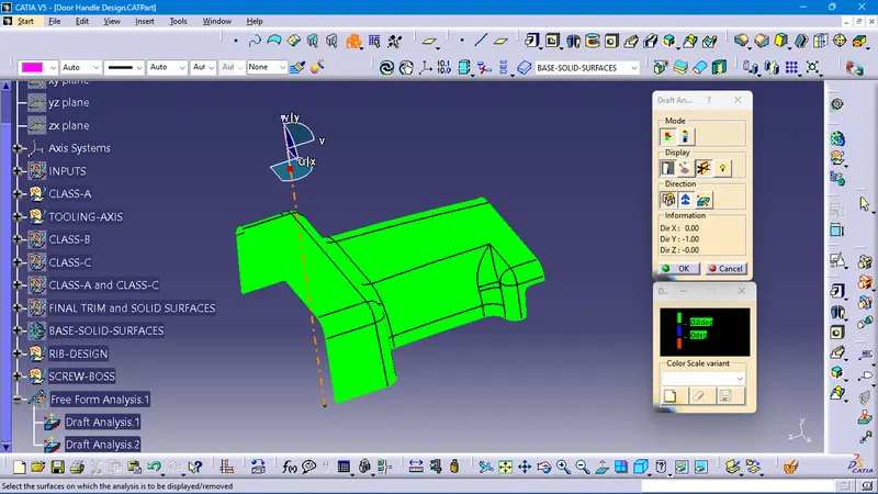
Green color - above 3 degrees positive draft
blue color- below 0 degree
Red color -between 3 and 0
CLASS-B SURFACE CREATIONS
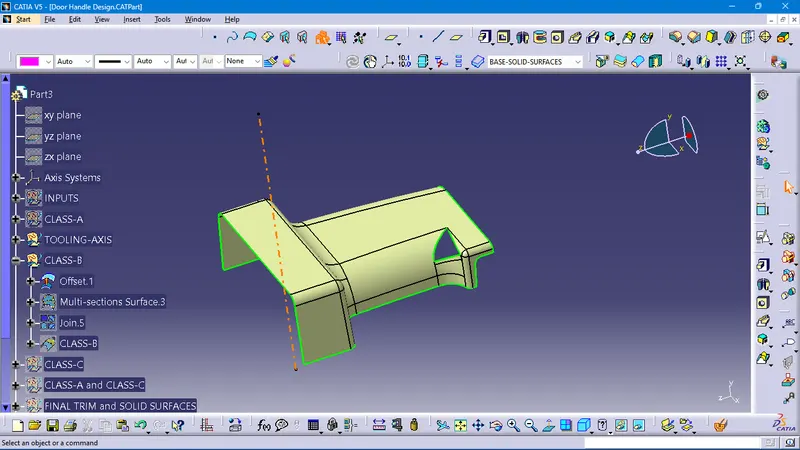
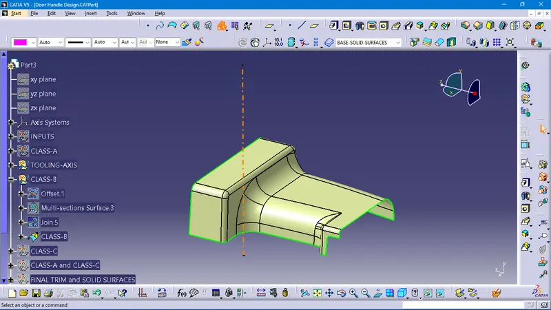
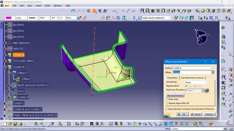
While offsetting the class-A surfaces to the inward direction with 2.5mm thickness. The multisection surfaces command solved the class-B surfaces by finding one gap surface, as given below.
CLASS-C SURFACE CREATIONS
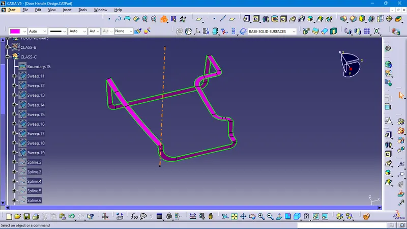
The surface of class C is created from class-A surface edges. Class C is often specified for interior surfaces not visible, and surfaces that will be covered by another part when assembledThe Class C finish allows more than Class A or B. or surfaces that the Customer feels do not need to meet a high finish. by using the below commands to get a class-C surface, like Boundary, sweep, spline, multisection surface, extrapolate, trim, and join commands.
CLASS-A with CLASS-B SURFACES
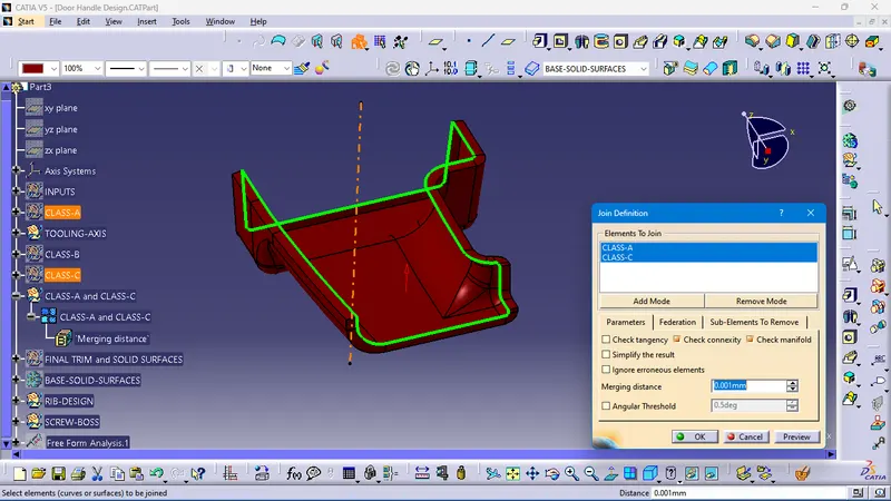
By Using The JOIN command to perform the final trimming operations
FINAL TRIM TO GET SOLID SURFACES
To perform the final trimming, select and JOIN the CLASS-A-With CLASS-C Surfaces and CLASS-B surfaces
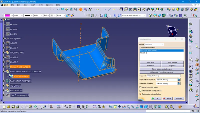
BASE and SOLID SURFACES
Go to Part design and make the final trim close body.
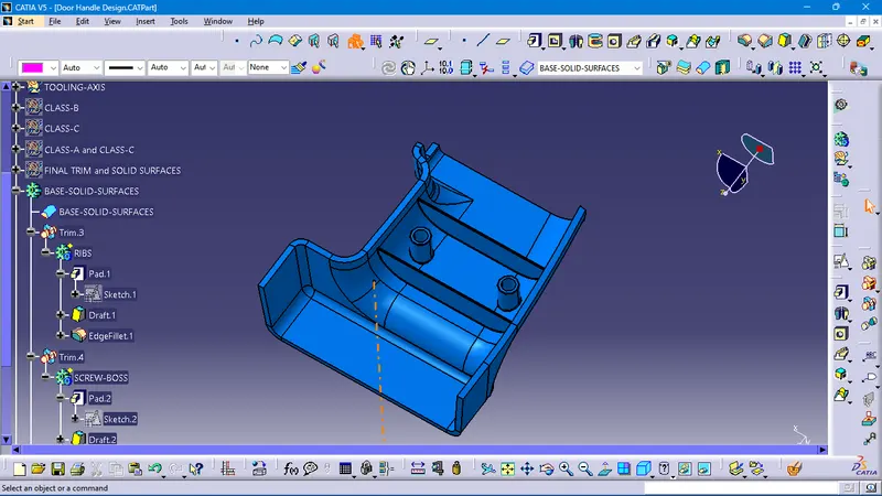
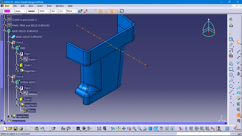
Then creation of RIB and SCREW BOSS according to the rules given in the question.
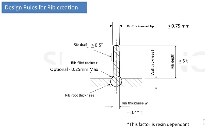
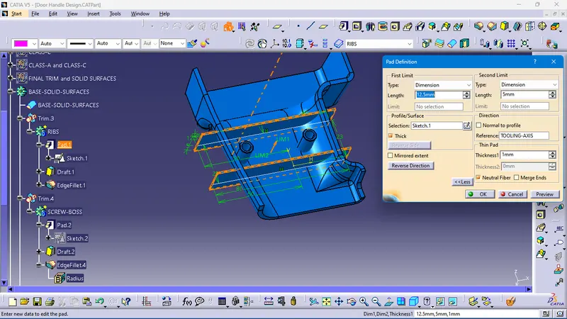
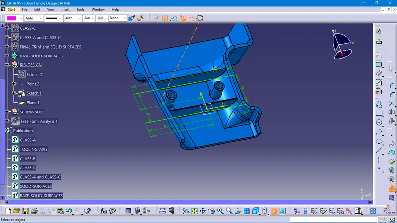
RIB Design begins with the proper geometrical set and uses the positioned sketches to get the rib sketch
t=2.5mm
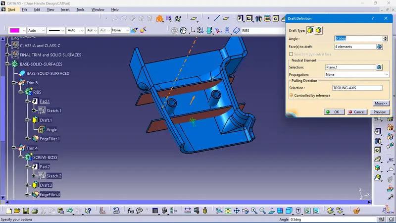
draft=0.5 degree
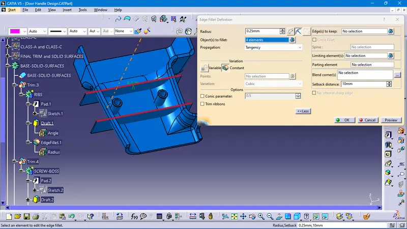
rib fillet=0.25mm
w=0.4*2.5=1mm
minimum rib tip thickness=0.75
Rib height=h=5*t
h=5*2.5=12.5
create a sketch for the rib and make it solid. and union trim it with the main body.
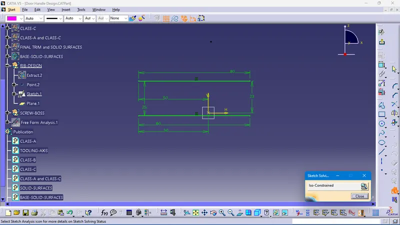
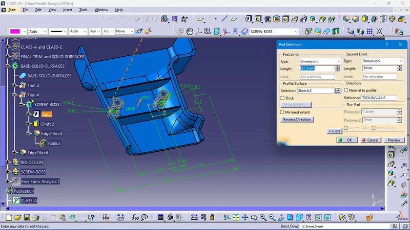
Next, the profile is extruded, to find the height,h=5 time of wall thickness
=2.5*5
= 12.5 mm
Therefore, the height is 12.5 mm
The draft angle is 0.5deg created as per the draft command.
completed with the rib edge filleted with a 0.25mm radius
SCREW BOSS-DESIGN
Screw Boss features are commonly found in injection molding designs. They are used to aid in the assembly of molded parts by providing a channel for a screw. Their primary use is to strengthen holes or slots in the surface present in the part model.
Design rules consider while creating a screw boss
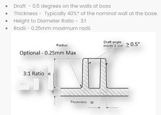
SCREW BOSS The design begins with the proper geometrical set and uses the positioned sketches to get the screw boss sketch
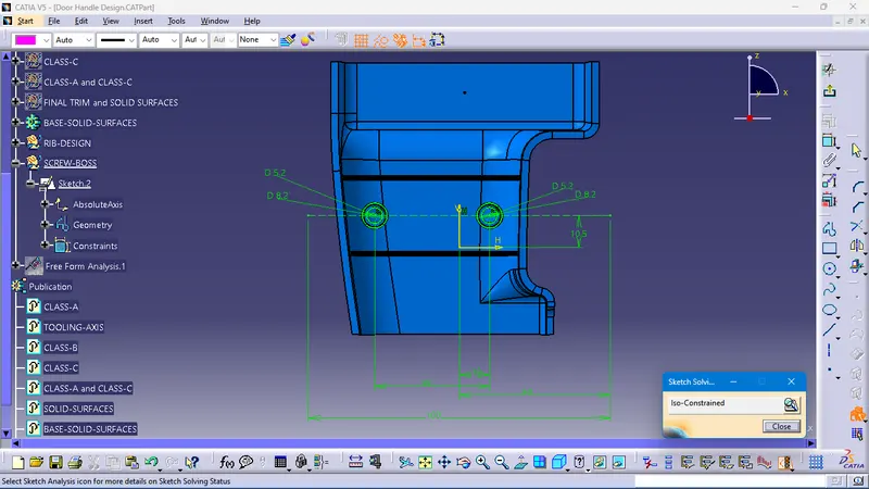
w=0.6*t=0.6*2.5=1.5mm one side
rib fillet radius=0.25 max
draft=0.5 degree
height to diameter ratio=3:1=12.5mm
Create a sketch and the create pad according to the rules. assemble it with the main body.
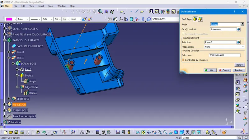
DRAFT ANALYSIS AFTER PLASTIC COMPONENTS CREATIONS
A DRAFT ANALYSIS has been completed based on the draft angle procedure by changing the degree angle from 0.5deg to 3 deg. to clear the class-A and class-C surfaces to comply with the producibility.
And also the publication of all major operations is identified in an orderly.
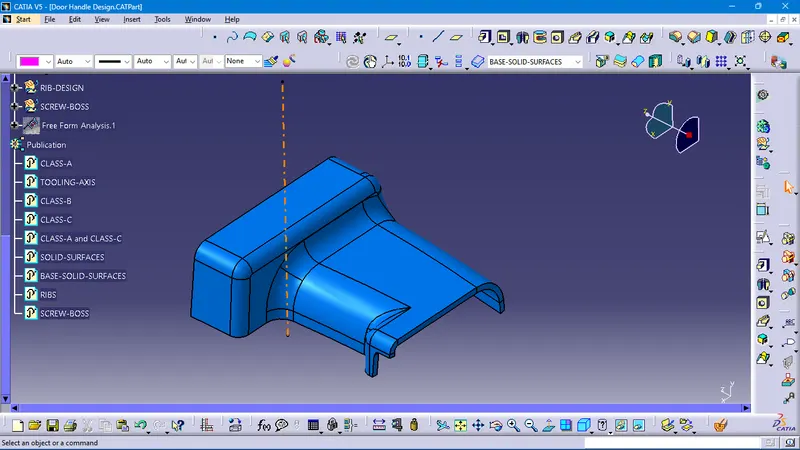
please refer to the attached file for your reference in detail.