Week 9 - Attachment Feature Creation (Ribs & Screw Boss) - Challenge 1
Attachment Feature Creation (Ribs & Screw Boss) - Challenge 1
Aim:To create B side feature Ribs and Screw Boss for given Drill Handle Class A Surface by considering Design Rules.
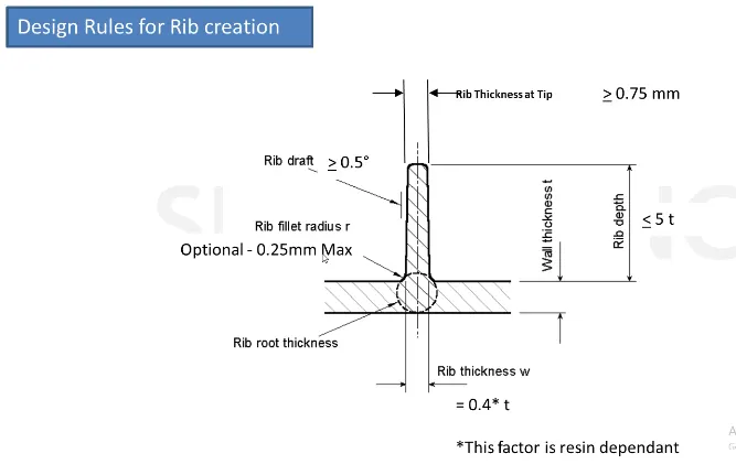
DESIGN RULE FOR RIB
DESIGN RULE FOR SCREW BOSS
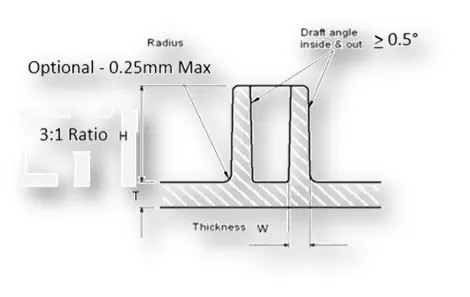
General Guidelines for Bosses:
- Draft - 0.5 degrees on the walls of boss
- Thickness - Typically 40%* of the nominal wall at the base.
- Height to Diameter Ratio - 3:1
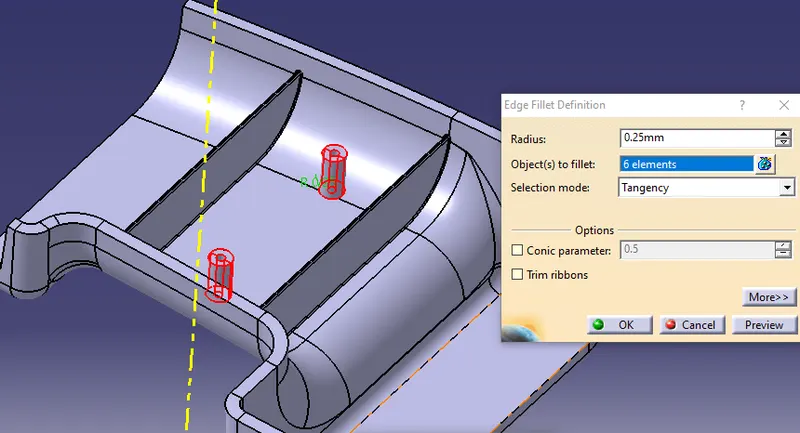
- Radii - 0.25mm maximum radii.
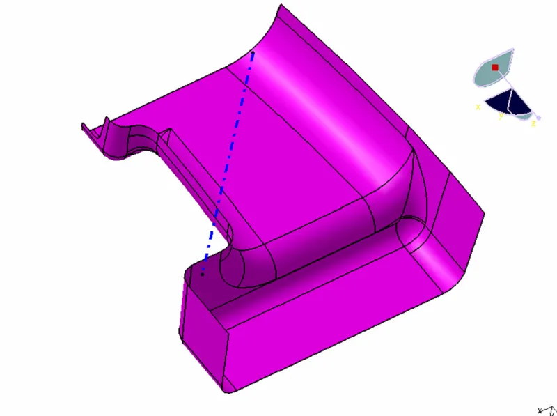
CLASS A SURFACE
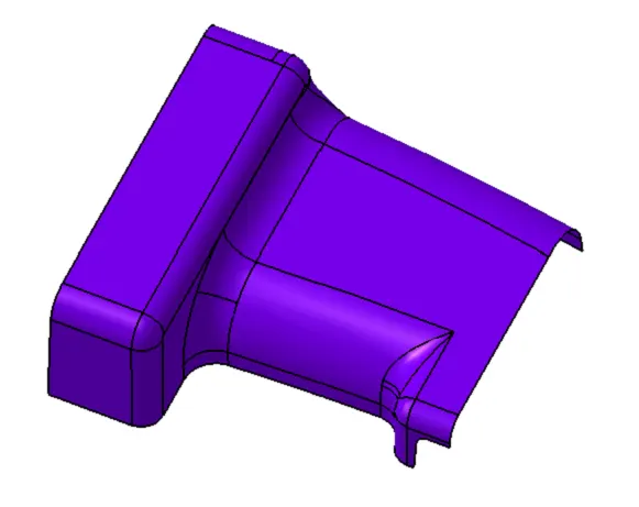
Checking Gaps In given A Surface
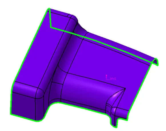
TOOLING AXIS CREATION
For creating tooling axis we have to choose correct direction where the given surface can be ejected and also considering the draft angle.
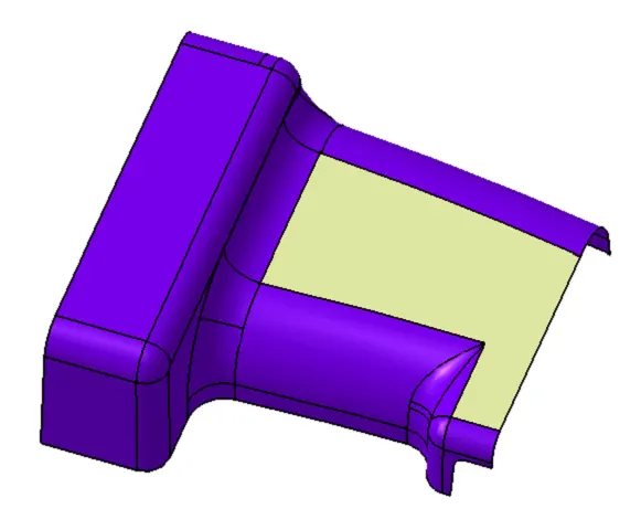
Extract
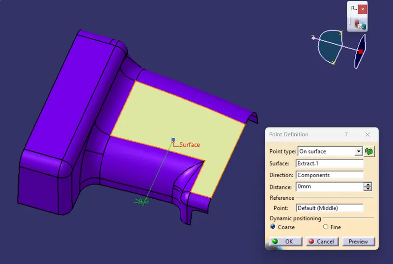
POINT
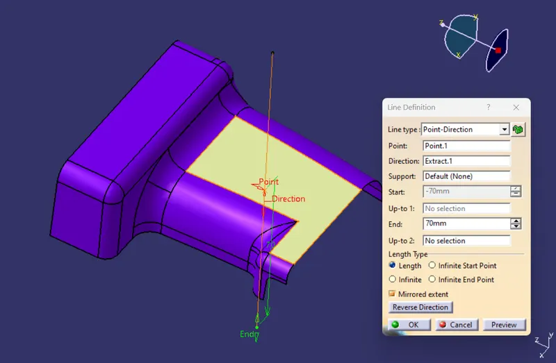
LINE THROUGH POINT
LINE 1
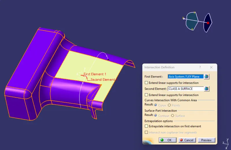
INTERSECTION
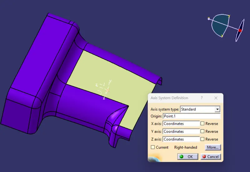
Create Axis System on Point
create intersection as shown in fig
Create lines
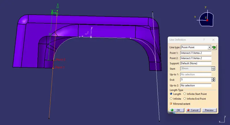
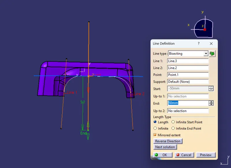
LINE 02
By using Bisecting create line 2
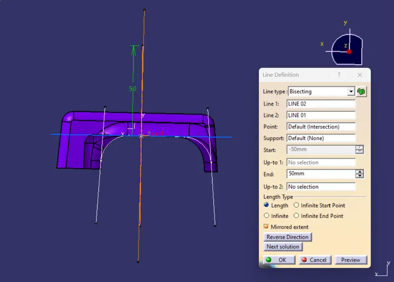
TOOLING AXIS
Bisecting LINE 01 AND LINE 02 tooling Axis is created
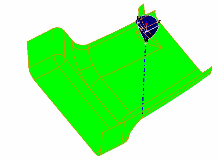
DRAFT ANALYSIS
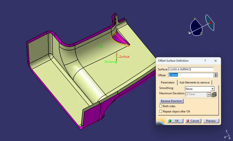
CLASS B SURFACE
OFFSET
BROKEN SURFACE
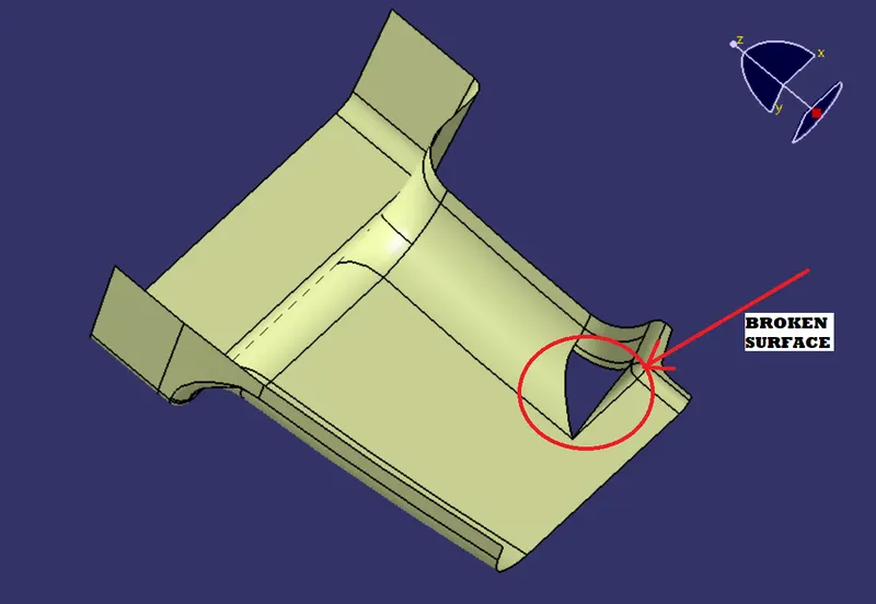
EXTRACT---> FILL
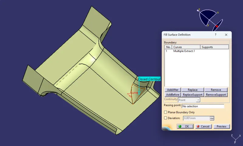
JOIN (CLASS B SURFACE)
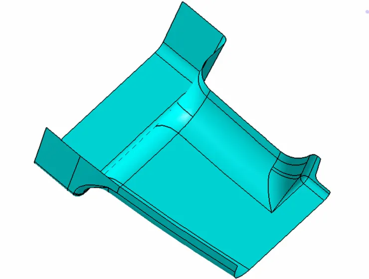
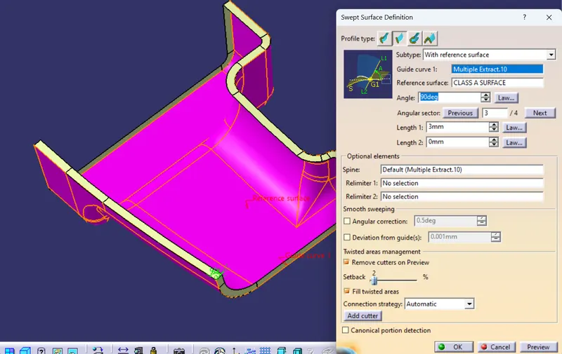
CLASS C SURFACE
Trim is done to Class B to Class C and to Class C Surface.
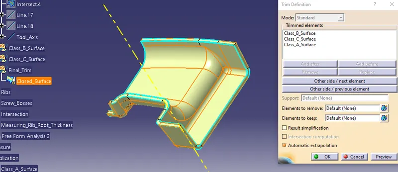
CLOSED SURFACE PART
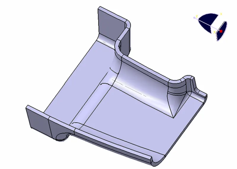
CREATING B SIDE FEATURES
RIBS
SKETCHES
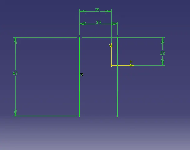
EXTRUDE
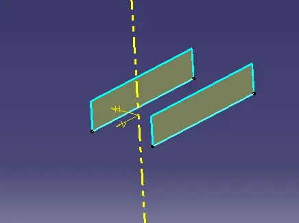
RIB Thickness as 1mm
By Considering Design Rule
i.e. 0.4 * t
wher t = Part Thickness=2.5
0.4*2.5=1mm
i given thickness on both sides 0.5mm.
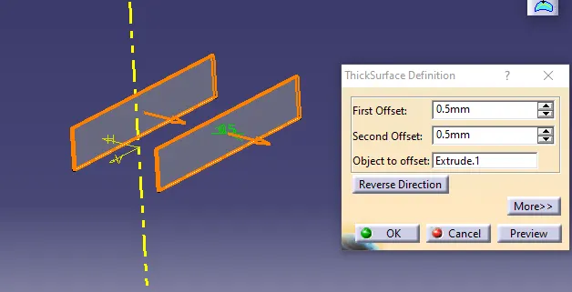
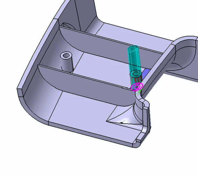
DRAFT
Draft is given as 0.5deg
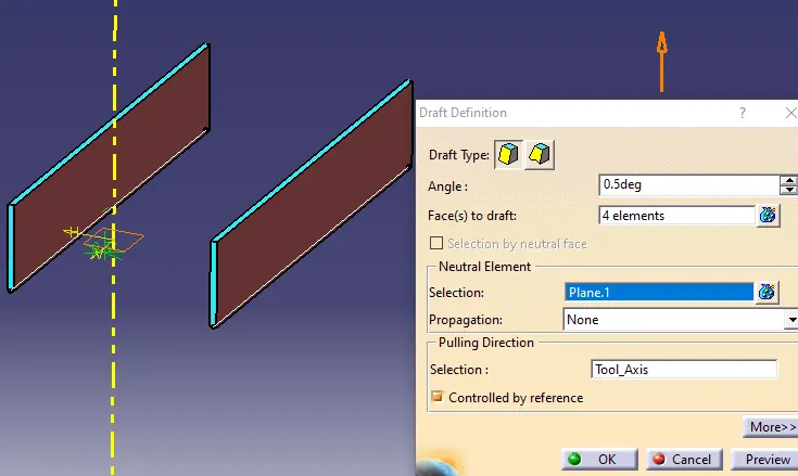
By using Boolean Operation i.e tri the ribs are added to main part body
FINAL RIB
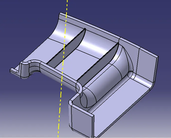
SCREW BOSS
SKETCHES
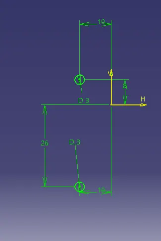
For creating screw boss design rules are followed
here wall hole dia is taken as 3mm and wall thickness taken as dia 3mm
because the nominal wall thickness is given as 2.5mm
i.e w=0.6*t
=0.6*2.5
w=1.5 since it is circle i have 1.5mm thickness to the extruded circular surface.
Here i have given 3mm thickness to the extruded surface at outer side.
Extrude
here also Height to Diameter ration is taken in to consideration
i.e H/B<3
HB=3��=3
Where B is dia of Hole
H is height of screw boss
H=B⋅3�=�⋅3
H=3*3
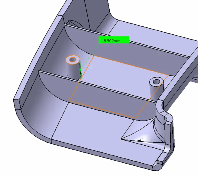
H=9mm
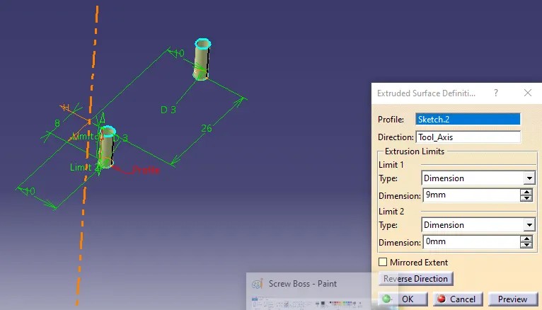
Measuring Distance
Draft
draft=.5 deg
Fillet Radius
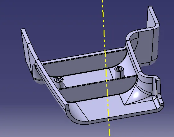
FINAL PART
DRAFT ANALYSIS
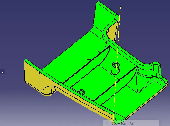
PUBLICATIONS
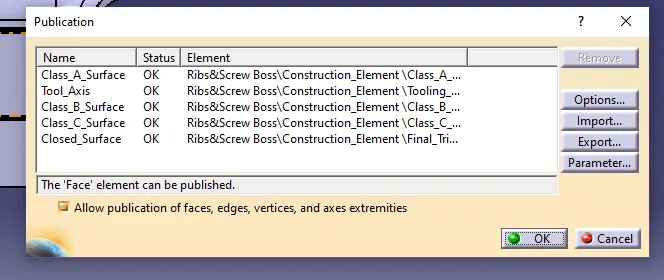
VIEWS
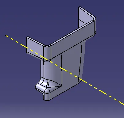
ISO VIEW
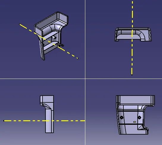
Other Views:
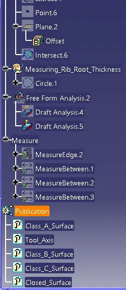
TREE STRUCTURE
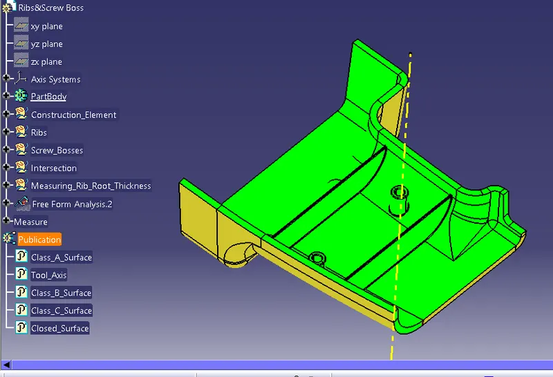
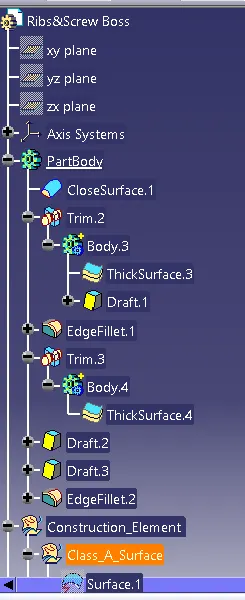
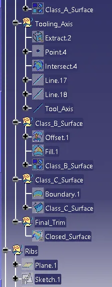
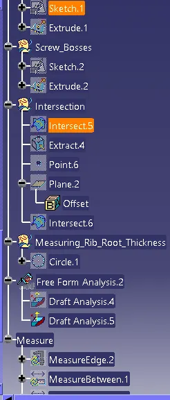
DETAILED TREE STRUCTURE
CONCLUSION
B side features are created for given Class A Surface
Note:
I have traid all 3 methods to create tooling axis at 2.9deg but the given Class_A_Surface as some issues so im unable achieve the draft angle exactly at 2.9deg so i have taken minimum draft angle of RIB & SCREW BOSSES at 0.49deg, and completed the draft angle.