Section Modulus calculation and optimization
AIM:
To calculate the section modulas of the hood and optimizing it for increasing the strength of the hood.
INTRODUCTION:
SECTION MODULUS:
Section modulus is a geometric property for a given cross-section used in the design of beams or flexural members. It does not represent anything physically. To define section modulus, It may be defined as the ratio of total moment resisted by the section to the stress in the extreme fiber which is equal to yield stress.
There are two types of section modulus:
- Elastic section modulus:
- Plastic section modulus:
A. Elastic section modulus:
For general design, the elastic section modulus is used, appling up to the yield point for most metals and other common materials. The elastic section modulus is defined as S=I/Y, Where I is the second moment of inertia (or area moment of inertia, not to be confused with the moment of inertia) and Y is the distance from the neutral axis to any given fibre. It is often reported using Y=C, where C is the distance from the neutral axis to the most extreme fibre. It is also often used to determine the yield moment(My)such that My=S x `sigma y`is the yield strength of the material.
B. Plastic section modulus:
The plastic section modulus is used for materials where elastic yielding is acceptable and plastic behaviour is assumed to be an acceptable limit. Designs generally strive to ultimately remain below the plastic limit to avoid permanent deformations, often comparing the plastic capacity against amplified forces or stresses. The plastic section modulus depends on the location of the plastic neutral axis (PNA). The PNA is defined as the axis that splits the cross-section such that the tension. So, for section with constant yielding stress, the area above and below the PNA will be equal, but for composite sections, this is not necessarily the case.
But here i have to calculate the elastic section modulus. The elastic section modulus is given by:
S=I/Y
S= Section Modulus
I= Moment of Inertia
Y= Distance between the neutral axis and the extreme end of the object
PROCEDURE:(Case-1)
For calculating the section modulus first I have to take an intersect of the outer panel and the inner panel of the hood with a plane. The intersection parameter is shown below:

Now i will join this gaps between in inner pannel intersection lines using line definition (Gaps in between those lines due to present of emboss)
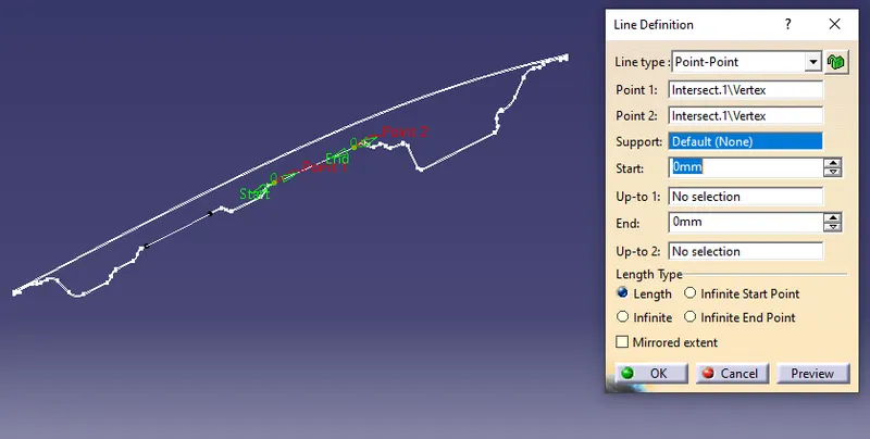
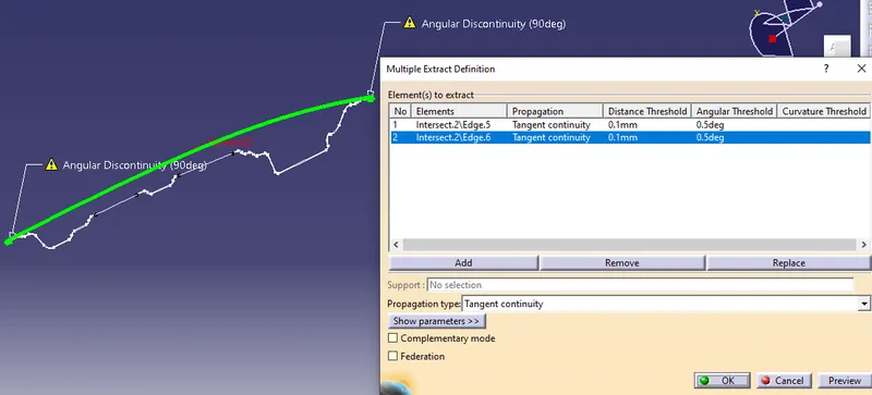
Now i will use the the multiple extracs feature and will extract the outer boundary of the outer panel or outer part of the hood.
The boundary is shown below.
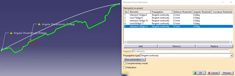
The same thing i will do for the inner panel as will extract the outer boundary of that. The boundary is shown below:
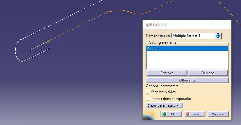
Now i have to join the inner panel boundary with the outer panel. But before that, I will split the extra portion of the inner panel. so for splitting, I will make a point on the outer boundary that i have just extracted and will use that point as the cutting element. The split is shown below.
A similar thing i will do to the other side and also then i will create two lines on each side which will be a point-to-point line to connect the inner panel to the outer panel to make it closed section. The lines are shown below:
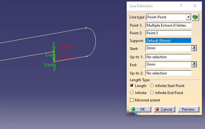
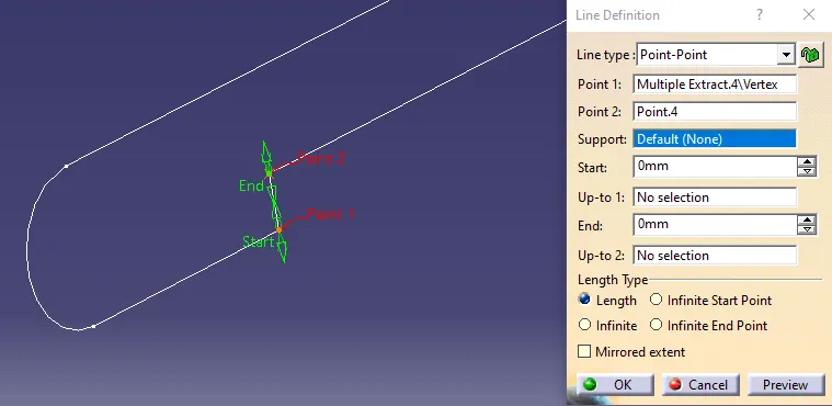
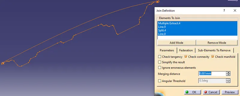
Then i will join the lines and the inner and outer panels. The join is shown below:
Then i will make the closed surface from this boundary. The closed surface is shown below:
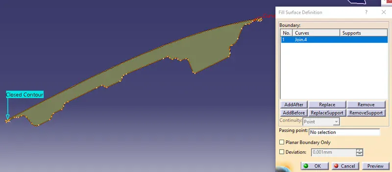
Then i will just go to the inertia measuring tool in CATIA which will be there at the bottom and measure it on the fill surface that i created. The inertia parameters are shown below:
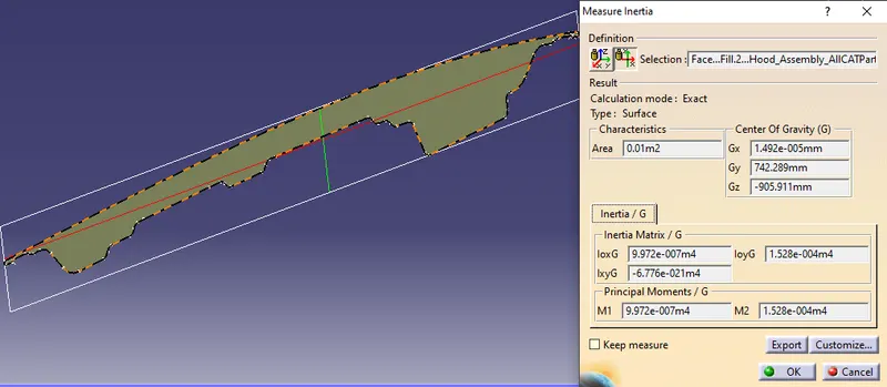
So here i got two values M1 and M2
M1 was`9.972e-007m4` and M2 was `1.528e-004m4`. Here you can see that values are in meters so i will just change into mm by multiplying `10^12`
Here i will select the lesser value of inertia between M1 and M2 so M1 is less than M2 so that will be my inertia value
Here now i got the value of I=`9.972*10^5``mm^4``
Now i have to calculate he value of Y which is distance between the neutral axis and the extreme end of the object.
So for calculating Y i will measure the distance between the extreme ends of the outer panel and then divide it by 2 to get the value of Y.
For measurig, I will create points and line on the extreme ends and measure them. The distance is shown below:
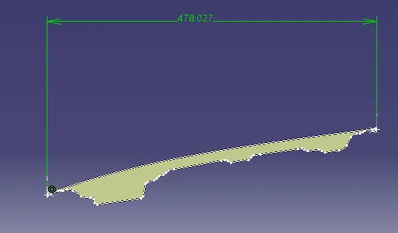
The distance between the two extreme ends i got was 478.027mm. I will just divide this length by 2 to get the value of Y
Y=478.027Y=478.027
Y=239.0135mm
S=I/Y =`(9.972*10^5)/239.0135`=`4.172*10^3 mm^3`
so now i have the values of both I and Y and will now calculate the section modulus(s)
Optimization:(Case-2)
Now i will optimize the above-calculated section modulus. optimizing means here i will try to increase the value of section modulus for increasing the strength of the component which is the hood. For optimization, i will neglect the thickness of the hood.
So for this, I will offset the boundary of the inner panel to 0.4mm which will increase the inner area and therfore increase the inertia also. The offset is shown below:
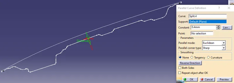
Now again i will follow the same procedure that is I will create the lines which will connect the two panels. Then I will just join the lines and boundary of both the panels. The join is shown below:
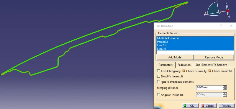
Then again i use the fill surface feature to make a surface. The surface is shown below:
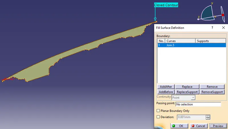
Now i will calculate the moment of inertia for this surfae. The moment of inertia is shown below:
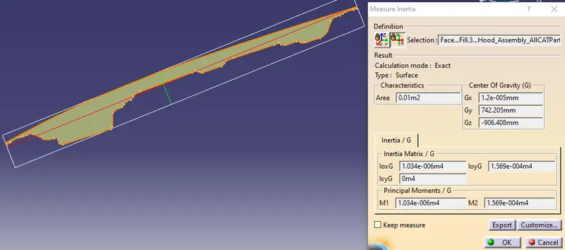
The new values of inertia i got were M1 was `1.034e-006m^4`and M2 was `1.569e-004m^4`again taking the minimum value of the two and converting the value into mm, The inertia value i got was`1.034*10^6mm^4`
The value of Y will be the same as it was for previous case that is 239.0135mm.
The new section modulus is:
S=I/Y= `(1.034*10^6)/239.0135`=`4.326*10^3 mm^3`
Optimization:(Case-3)
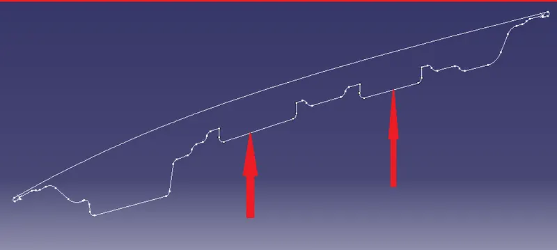
Now again i will optimize the above-calculated section modulus. optimizing means here i will create few more embosses for increasing the strength of the component which is the hood.
so for this, I wil create two more embosse as shown in below image
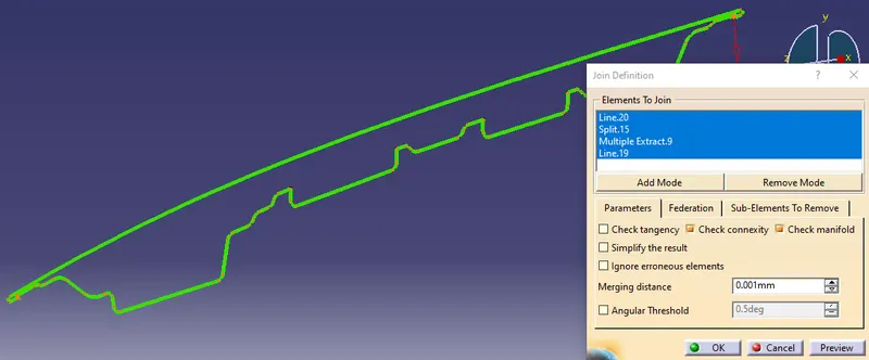
Now again i will follow the same procedure that is i will created the lines which will connet the two pannels. then i will just join the lines and boundary of both the panels. The join is shown below
Then again i use the fill surface feature to make a surface. The surface is shown below.
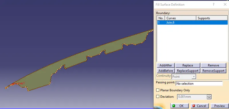
Now i will calculate the moment of inertia for this surface. The moment of inertia is shown below.
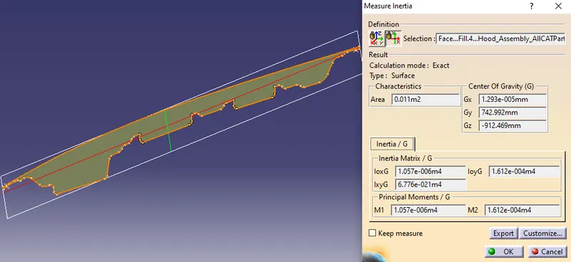
The new values of inertia i got were M1 was `1.057e^-006 m^4`and M2 was `1.612e^-004 m^4`again taking minimum value of the two and converting the values into mm The inertia value i got was `1.057*10^6 mm^4`
The value of Y will be the same as it was for the previous case that is 239.0135mm
The new section modulas is:
S=I/Y=`(1.057*10^6)/239.0135`=`4.4223*10^3 mm^3`
Result: The values of secion modulus i got are shown below :
| SL NO | Moment of inertia (I) in `mm^4` | Distance between the neutral axis and the extreme end of the object(y) in mm | Section modulas (S) in `mm^3` |
| 1 | `9.972*10^5` | 239.0135 | `4.172*10^3` |
| 2 | `1.034*10^6` | 239.0135 | `4.326*10^3` |
| 3 | `1.057*10^6` | 239.0135 | `4.422*10^3` |
As u can see in the above table the initial value of section modulus i got was `4.172*10^3`but after optimizing it i got the value as `4.422*10^3`which shows that the strength of the component in that section is increased.
Conclusion :
The above calculation shows that Case-3 optimization has a greater section modulus than Case-2 and Case-1.
All these calculations are essential while designing to know the strength and load-carrying capacity of the given component.
It is quite evident that increasing the more number of embooses has a significant impact on increasing the section modulus which in turn it's strength also. But it also depends on the designer to choose the best option from the calculation that gives satisfactory results.