Week 9 - Attachment Feature Creation (Ribs & Screw Boss) - Challenge 1
DOOR HANDLE DESIGN
First of all I got the class a surface then I created tooling axis, class b, class c and close body in several steps.
TOOLING AXIS – I took a surface and extract it then I created the point using surface and give the value zero after that I crated a line using point-direction method and give the direction as y component. At last I named it as tooling axis.
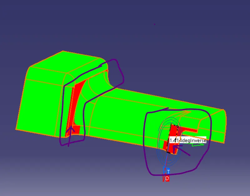
DRAFT ANALYSIS 1 – For draft analysis I take feature draft analysis command and place the compass on tooling axis and pick the class a surface and give the clearing angle 2.9 degree as green color. After picking the class a surface it`s shown as fully blue color and when I changed draft direction then it`s turned into green color and somewhere also red color.
NOTE-For red color I check the draft angle of that part it`s shown as 1 to 1.5 degree. After that I confirmed from support session that some error in class a surface.
CLASS B – For creation of b surface I took the class a surface and offset it by 2.5mm. after offsetting class a surface I took the multiple extract command and pick the all offset surface with no propagation mode. In multiple extract there was a hollow surface then I take the extract command and pick the inner boundary and extract it. After doing extract I took the multi section surface command and pick one edge as support and other two as guide and done the process. After that I join the multiple extract 1 and multi- section 1. At last I named it as b surface.
CLASS C – 1- For class c I took the outer edges of class a in four part`s. after that I took the sweep command with reference surface and for guide curve I pick the boundary 1 and reference surface I pick the class a surface and give the draft value 93 degree and length 4mm then I got sweep 1.
2- I took the sweep command with reference surface and for guide curve I pick the boundary 2 and reference surface I pick the class a surface and give the draft value 93 degree and length 4mm then I got sweep 2.
3 - I took the sweep command with reference surface and for guide curve I pick the boundary 3 and reference surface I pick the class a surface and give the draft value 90 degree and length 4mm then I got sweep 3.
4 - I took the sweep command with reference surface and for guide curve I pick the boundary 4 and reference surface I pick the class a surface and give the draft value 90 degree and length 4mm then I got sweep 4.
After creating sweep surface I look that there were some gap in each other so extrapolated them. First I extrapolate the sweep 1 in two part by 5mm with curvature continuity then I extrapolate the sweep 3 in two parts by 5mm with curvature continuity. After that I extrapolate the sweep 4 in two parts by 5mm with curvature continuity and then I extrapolate the sweep 2 in two parts by 5mm with curvature continuity. After that I trimmed extrapolate 5, extrapolate 2, extrapolate 8, extrapolate 6. At last I named it as c surface.
CLOSE SURFACE – For close surface I join the class a with c surface then trimmed it with class b. I got the close surface.
CLOSE BODY – For close body I went to part design workbench and create the body and took the close surface command and pick the trim then I got the close body.
RIB AND SCREW BOSS
RIBS – For ribs I took the multiple extract command and extract the inner surface close body then I create a point with surface method and give the value zero. After that I create ZX plane on point 2. After that I create position sketch for reference I pick the close surface face 1 and for projection point I gave it as point 2. In position sketch I create two line and give it as output feature. After that I extrude output 1 for profile tooling line and for length 12mm one side and other one give 1mm. After that I extrude output 2 for profile tooling line and for length 12mm one side and other one give 1mm. the height of rib according to law is 5 times of thickness of component.
After that I create two body rib 1 and rib 2 then I went to part design and took the thick surface and pick the extrude 2 and give the value 1mm according to law 0.4 times the thickness of component. After that I took the thick surface command once again and pick the extrude 1 and give the value 1mm. After that I gave the draft on rib1 and rib 2 one by one. For draft I pick the outer four surface of rib and gave draft value 0.5 degree. The rib tip thickness was more than 0.75mm.
After that I add the close body with rib1 and rib 2. After that I give the edge fillet .25mm all edges of ribs.
SREW BOSS – For screw boss I create position sketch for reference I pick the close surface face and for projection point I pick the point 2. For screw boss I took m6 bot feature to create. I create four circles for two I gave the diameter 8.2mm and other two I gave 5.2mm.
After that I went to part design workbench and pad the sketch 2 by 12mm.according to law height of screw boss 5 time the thickness of component. I create a body and named it as screw boss and gave the draft for draft angle I gave it as 0.5degree. after that I add it to part body and gave edge fillet 1mm.
DRAFT ANALYSIS 2 – For second draft analysis I took feature draft analysis and pick part body and gave draft value .45degree then it`s turned into blue and green color.