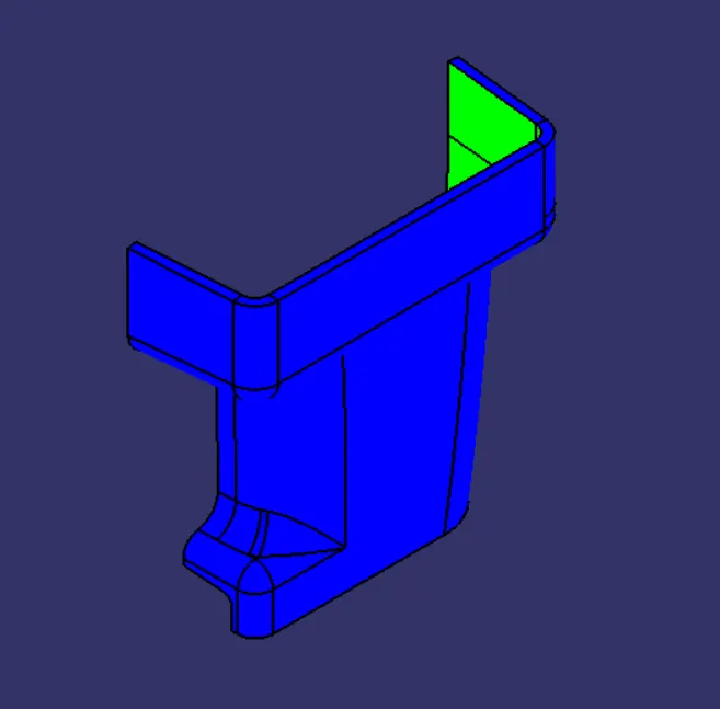
Week 9 - Attachment Feature Creation (Ribs & Screw Boss) - Challenge 1
AIM:
- Create the Rib and Screwboss for the Drill Handle considering the design rules.
Tooling Axis:
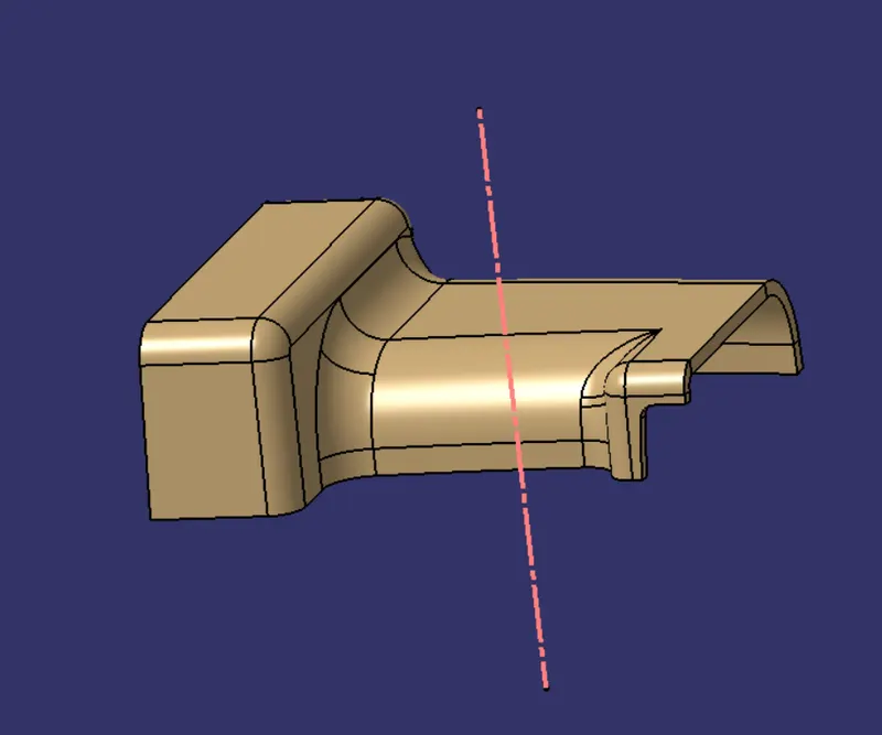
- The direction in which the mould open and closes is called the tooling axis direction.
- Here, using project intersection along xy plane is created and the two inclined lines were drawn inside the positioned sketch.
- Then bisecting lines with the two inclined lines were drawn.
- Thus, the tooling axis is drawn.
Class A surface:
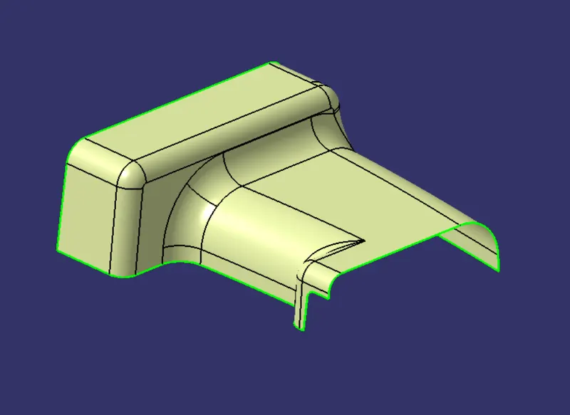
- After receiving the clasa A surface check the connectivity of the surface using join or by boundary.
- If it is not join together make it with a minimum tolerance of 0.001 to 0.003 and check for connectivity of the surface.
Class B surface:
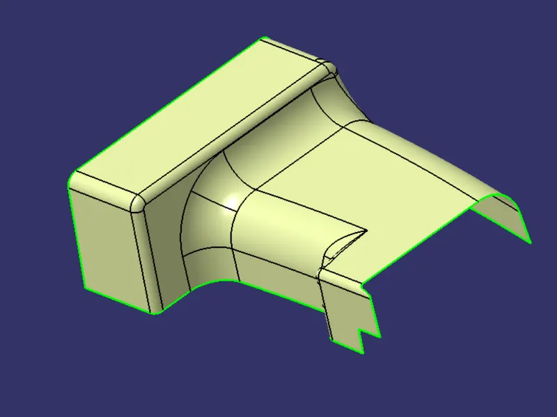
- Class B surface is created by offesting the Class A surface for 2.5mm (according to the thickness).
- The patches which are formed after offesting are closed using commands like extract ,extrapolate, multisections and trim.
Class C surface:
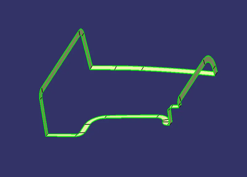
- For Class C surface the outer boundary of the Class A surface is taken and using the sweep command with both reference to surface and draft direction Class C surface is created.
Final Solid Component:
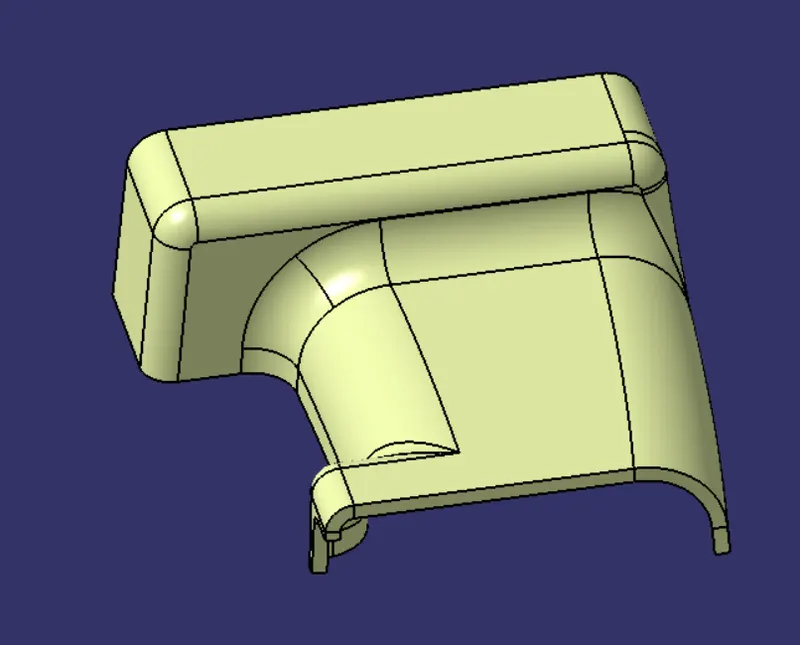
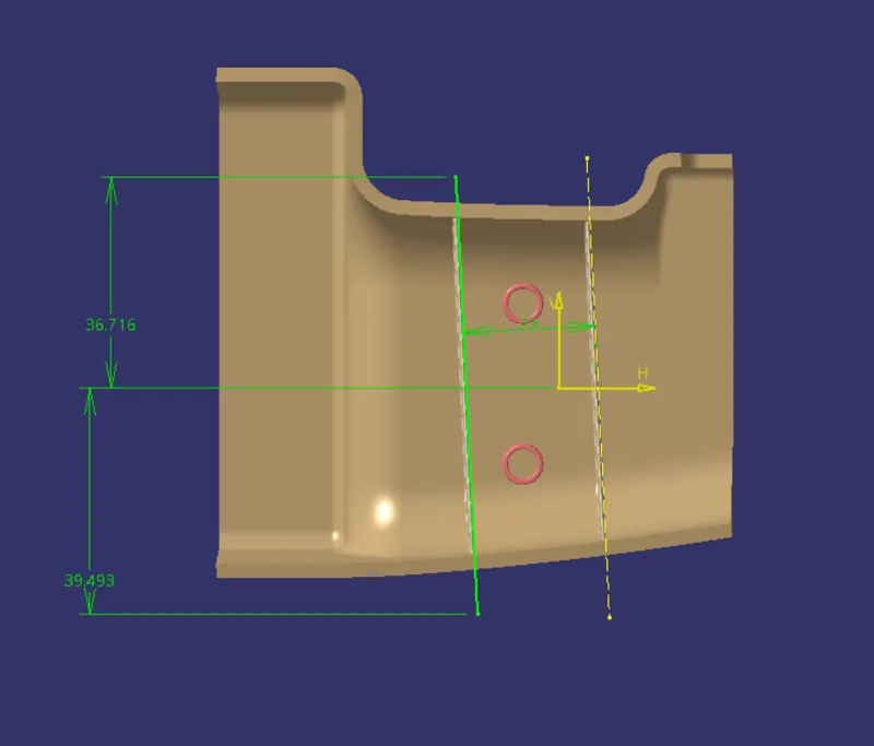
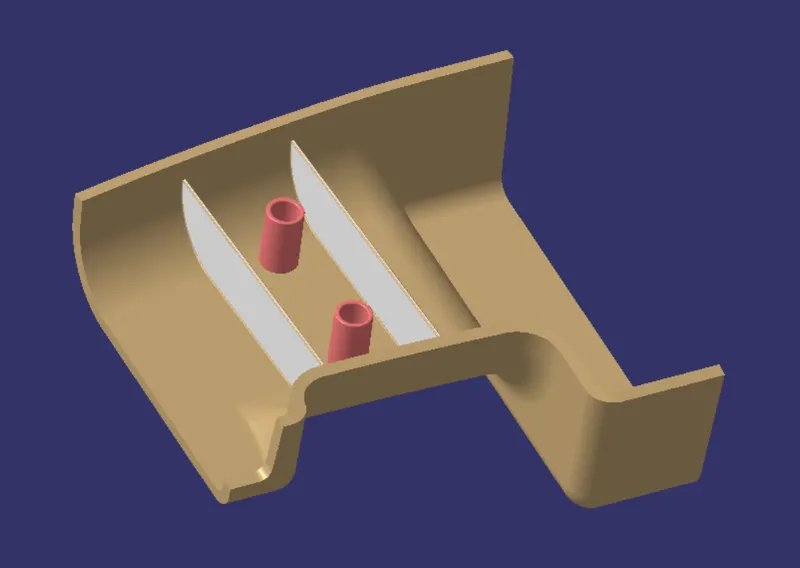
Ribs:
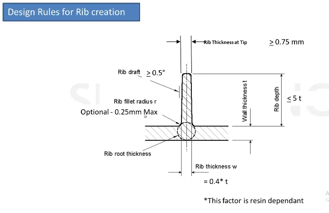
- Ribs are a feature in plastic injection molded parts. They are thin extensions that run perpendicular from a wall or plane. They are commonly used to provide additional support and strength to a part.
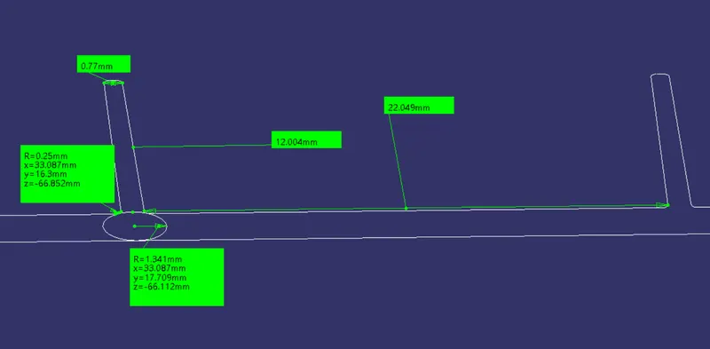
Sketch for Ribs:
Rib-1:
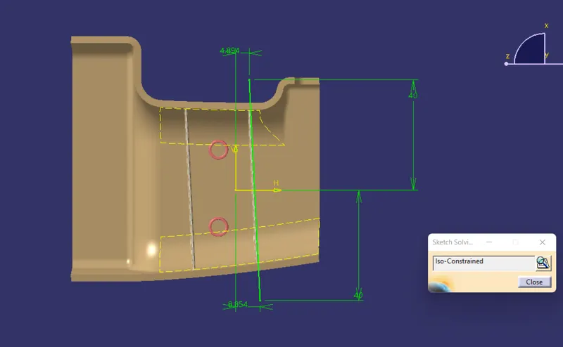
Rib-2:
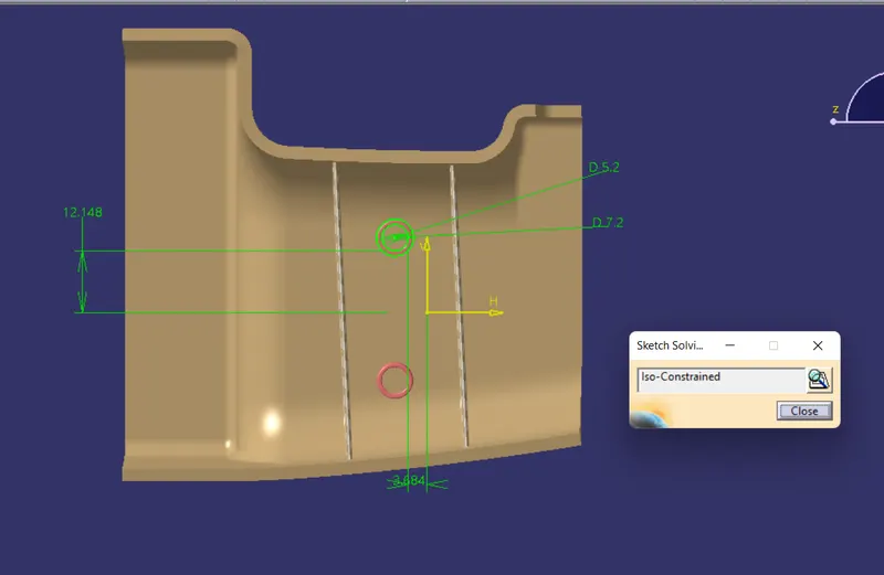
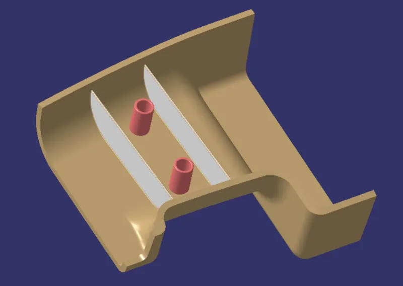
SCREW BOSS DESIGN:
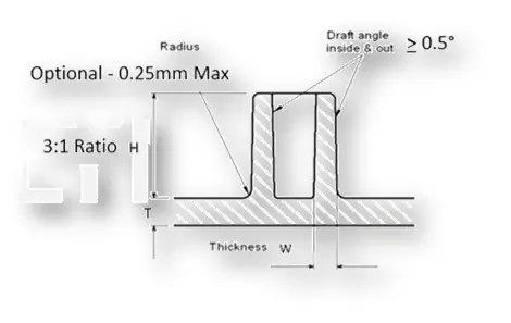
- Bosses are projections designed to accept inserts, self-tapping screws, etc. for use in mounting, fastening or assembling parts.
Sketches of Screw Boss:
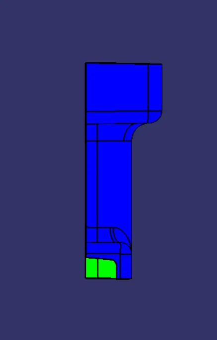
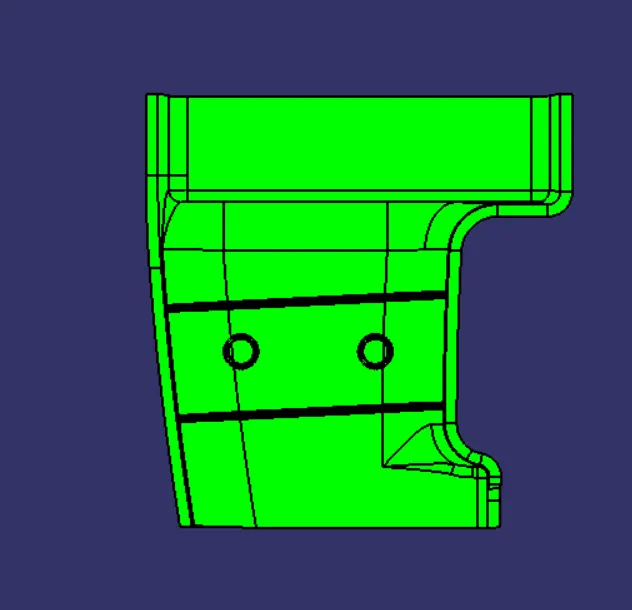
Draft Analysis of Final component in various orientations:
FrontView:
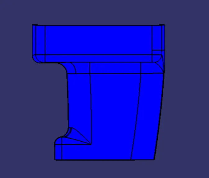
SideView:
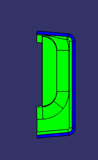
TopView:
IsometricView: