Week 9 - Attachment Feature Creation (Ribs & Screw Boss) - Challenge 1
AIM :
To create a Door Handle Plastic Component using the given Class 'A' Surface and by using the Closed Surface Feature to create a solid part from the surface and create a B Surface Attachment features Ribs and Screw Bosses.
REPORT :
This report demonstrates the design of an Automotive Plastic Component – Door Handle (Plastic) and the creation of Ribs & Screw Boss using industry principles such as Draft angles, Draft Analysis, Determining and implementing of Tooling Axis, Class A, Class B, and Class C surfaces. The component is designed using Surface Design and Solid Design techniques in CATIA V5.
OBJECTIVE :
- Conduct a Draft Analysis on the Class A surface for the Door Handle Plastic component for determining the appropriate Tooling Axis.
- Creation of other surfaces i.e. B & C Surface for creating a solid component
- Create an Attachment featuring Ribs and Screw Bosses on the created Class B Surface.
- Performing the final Draft analysis for the inspection and checking if all the features are above the Nominal Drafting for the creation of the Solid Model.
STEPS FOLLOWED:
- Tooling Axis Creation.
- Draft Analysis of Class A surface.
- Creating Class B surface and Class C surface.
- Creating a Closed body of the component Door Handle.
- Draft analysis for Door Handle Component.
- Creating the Sketches of Ribs & Screw Boss profile as per the given guidelines.
- Solid Profile creating for the Ribs & Screw Bosses using Thick Surface and Pad Commands. Added them to the Closed Partbody.
- Given the Draft angle and Edge Fillet Radius to the required faces as per the Guidelines.
- Check the parameters of Ribs & Screw Bosses as per Guidelines and standards.
- Perform the Draft Analysis for Ribs and Screw Bosses Assembly.
THEORY :
The terms are briefly explained below:
1) DRAFT :
The draft is an angular tapering given at the design stage to every Plastic Component that has to be manufactured. It is given in the direction of the Mold Movement. The Draft allows the parts to release easily from the mold without creating friction between the surface of the component and the core and cavity plates.
When a Plastic component cools down inside the mold, its natural tendency of it is to shrink and attach to the core or cavity half. The movement of the mold opening causes friction on the walls of the component as well as the core/cavity blocks. This reduces the life of the mold as well as the component itself. The component may also have a rough surface finish as well as a weak structure due to this. This problem can be solved by giving a draft to the component.
Most applications require minimum draft angles of around 0.5º to 1º however, 3º draft angles are widely accepted for cost-saving purposes. 7º Draft angles are given to textured surfaces like Instrument Panels. Minimum possible draft angles are given to screw bosses, ribs, and stiffeners due to their critical nature.
2) DRAFT ANALYSIS :
Draft Analysis is a tool in CATIA that identifies the zones which deviate from the specified values of angles along a defined draft direction using color codes. Draft analysis is the first step performed after receiving the Class A of the component. Draft analysis should be passed in order to make the plastic component manufacturable. Acceptable draft angles are used as a range for draft analysis.
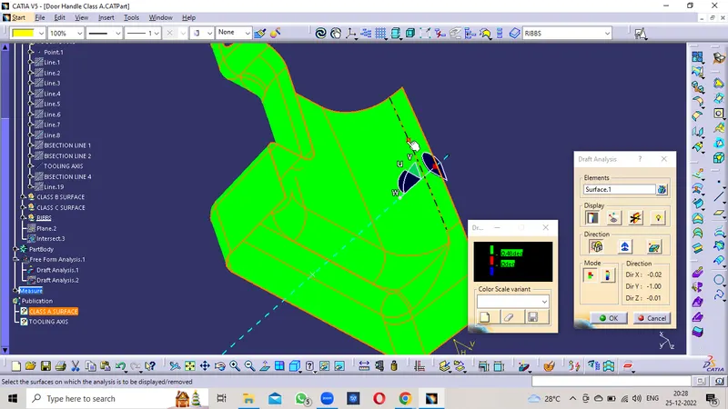
For Analyzing the Draft of the Class A Surface:-
- Change View Mode Customization to Material mode
- Go to INSERT ----> ANALYSIS ----> FEATURE DRAFT ANALYSIS.
- Select the compass from the dialog box, and move the compass to the Tooling Axis.
- Click on the surface to apply the color region on the component.
- Change the range to 0º to 2.9º. Apply the settings as shown in Figure.
- As shown the target area has a 0º draft angle which was the concerned face since it's a flat surface.
- Thus, it passes the criteria of having a suitable draft and the Class A can be further designed into a solid plastic component and manufactured.
3) TOOLING AXIS :
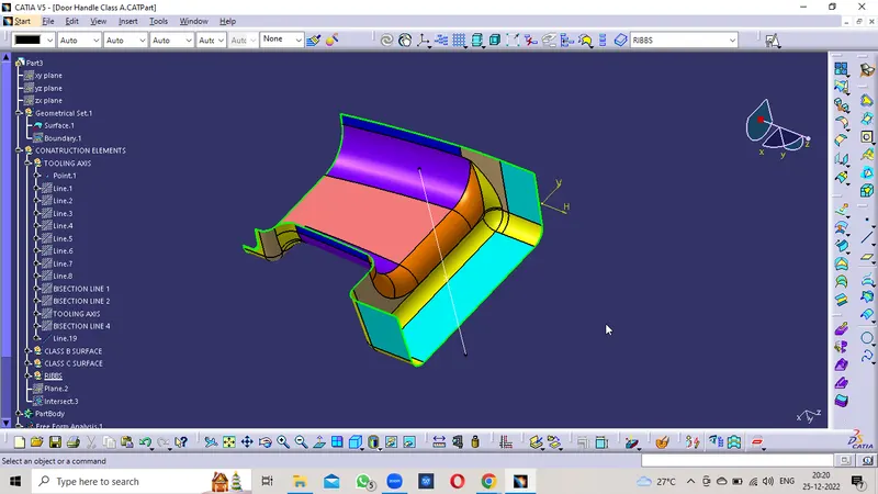
The tooling Axis is the direction in which the Mold opens and closes. Part Drafts are given along this axis. Identify faces that can potentially create problems while manufacturing. Surfaces at angles along a desired Tooling Axis. Extract a plain surface and create a point on its center for Axis system creation. In this case, X-axis can be a possible Tooling Axis Direction.
4) CLASS A SURFACE :
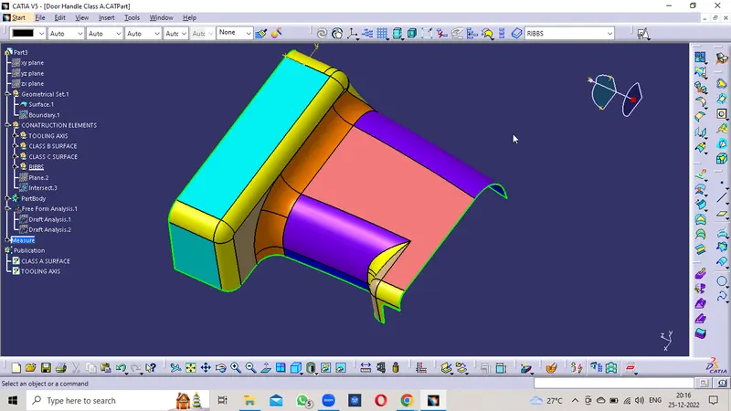
In automotive design, a class A surface is any of a set of freeform surfaces of high efficiency and quality. It is the visible aesthetic surface of any automotive component. Class A surface refers to those surfaces which are visible and abide by the physical meaning of a product. This classification is primarily used in the automotive and increasingly in the consumer goods industry. It is a requirement where aesthetics has a significant contribution. For this reason, the exterior of automobiles is deemed Class-A.
5) CLASS B SURFACE :
Class B surfaces are Engineering Surfaces that are invisible to the eyes or often on the back side of the Class A surfaces. It is mainly the thickness of the component or Class A. These surfaces need to be designed as per the Class A surface i.e., the continuity, thickness of the component, functionality, etc should be maintained. These surfaces include the main engineering features such as Screw bosses, Ribs, Snaps, Stiffeners, and fixations. B surfaces also do not contain any aesthetic styling content and textures since it is not visible to the eyes.
6) CLASS C SURFACE :
Class C surfaces are connectors between Class A and B surfaces. This surface connects both A and B surfaces along the Tooling Axis. It contains the draft as per the design. It is basically the thickened surface between both A and B surfaces.
OPERATIONS :
1) Creation of B surface :
- Checked the Class A surface is a Closed profile by using the Boundary command. The complete profile has only one Boundary at the outer edge without breakage.
- Offset the relevant surfaces from Class-A surface, the offset length is 2.5 mm since the thickness is 2.5 mm.
- Offset the Class A surface for 3mm (The thickness of the Component is 3mm).
- The offset surface has a Patch that the minimum fillet value places can't be offset.
- The simple method is done by using the Multi-Section Surface.
- Create a Boundary on the Two sides of the profile and the Multi-Section Surface command is used.
- The obtained Profile is Joined with the Offset Profile.
- The profile is closed completely without gaps or patches and the edges are formed on it.
- The B surface exterior is Extrapolated in the boundary for the Trim with Class A and C surfaces.
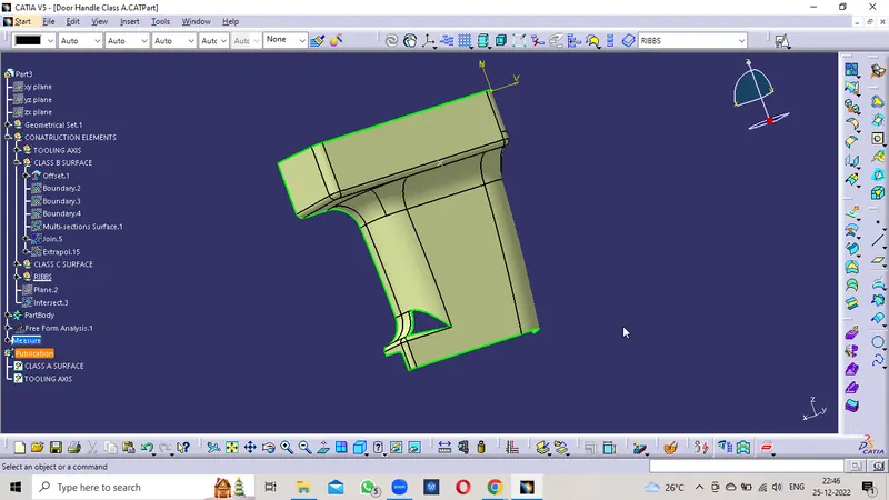
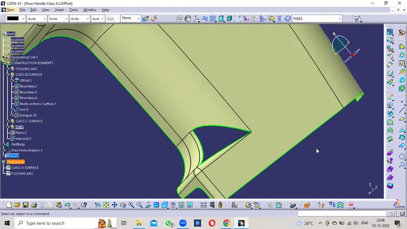
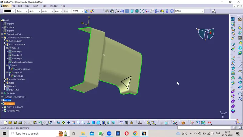
Here the Class B surface is created.
2) Creation of C surface :
- Using the Boundary feature, create a boundary on the surface edges of the Class A Surface.
- The sweep option is carried on the boundary lines to create a draft length extension (5mm) and draft angle (87°). Here instead of taking 90°, we have to take 87° because of some inclination and for trimming with the Class B surface (the 3deg will give the Draft clearence while manufacturing).
- Then the Class C surface is Joined with the Class A surface by using the Join Command.
- After the Sweep and join Operation, the Class B surface and the joined surface are trimmed with each other in order to create the Class C surface.
- Finally, Join the Class A Surface and the trimmed Surface to create the Final component.
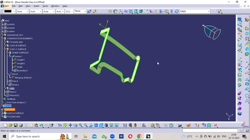

3) Creation of Closed surface :
- The Trimmed surface is formed.
- Created a boundary on the Trimed Surface so that it insures that no boundary formed.
- Confirms that it is completely closed.
- By using the Closed surface Command in the Part Body Design to the surface body.
- Now the Solid Body is formed.
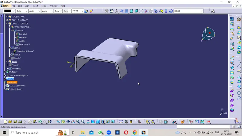
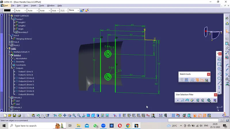
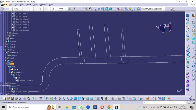
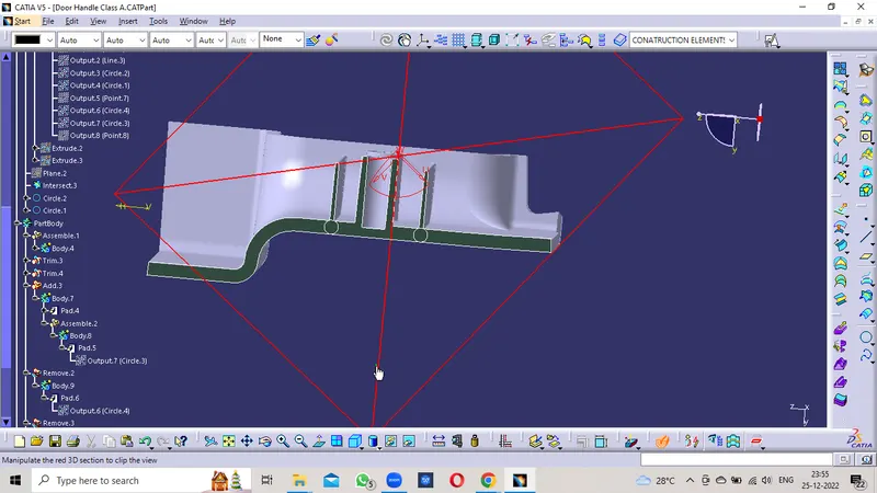
4) Creation of RIBS :
- Extract the B surface from the Trimmed profile.
- Select the Extracted surface as the Reference Plane and Origin point as the projection point in the Positioned Sketch.
- Create a line on the surface and give the appropriate dimensions to it.
- The distance between them is also provided to it.
- Now the Lines as the Output Feature for easy access.
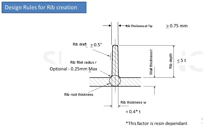
- Extrude the Line in the Tooling Axis Direction at a height of 13mm (Height < 5*thickness of component, H<3*5=15).
- By Thicken the Extruded surface at 1.2mm Thickness by Thick Surface Command in Part Body (Thickness = 40% of the thickness of component, =0.4*3mm, =1.2mm)
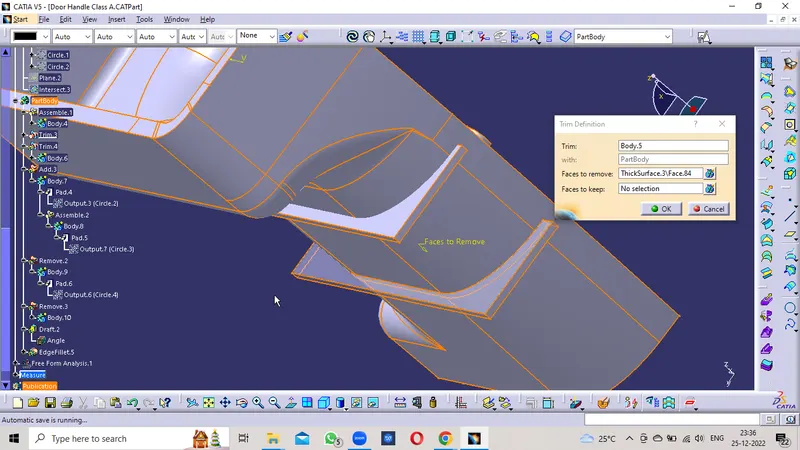
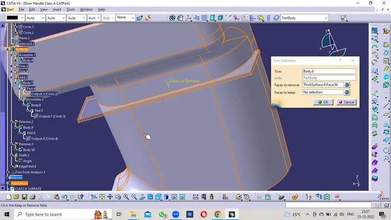
- Unitrim the Ribs with the Closed Body to remove the Excess Profile at the bottom side on the Class A surface.
- Similarly done for the other Rib also.
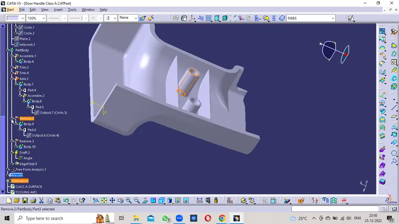
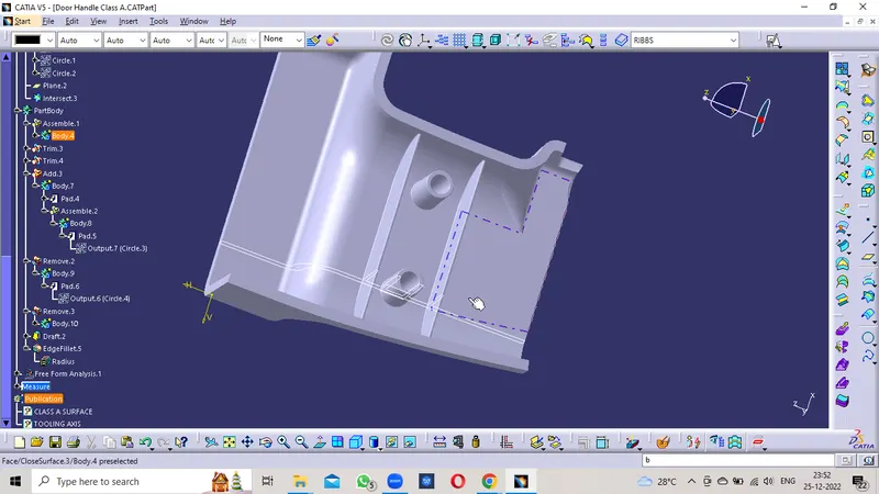
5) Creation of SCREW BOSSES DESIGN :
- The circles are Drawn on the Extracted Plane.
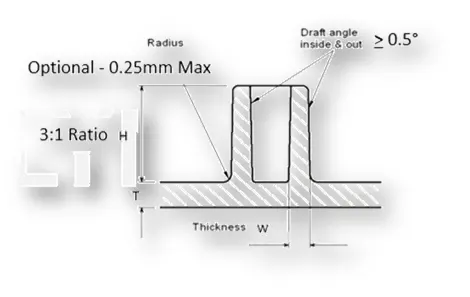
- The dimension is taken as the 5mm diameter ie. M6 Diameter is 5.2mm.
- The thickness of Bosses = 0.6* thickness of component, =0.6*3mm, =1.8mm.
- So the outer radius is 5+1.8+1.8 = 8.6mm.
- The Height should be a 3:1 ratio of diameter to height. The diameter is 5mm so the height is 15mm.
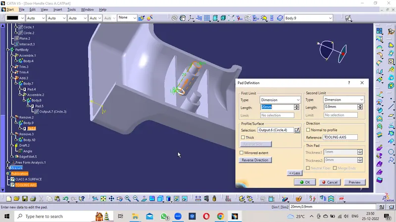
- The Outer and Inner Profiles are Output features.
- Both profiles are extracted by the Pad command.
- The Outer Profile is Added to the Part Body. The Inner Profile is Removed from The Part Body.
- The Dimensions of the Ribs & Screw Bosses as per the Guidelines are mentioned below.
Design rules for RIB :
Design rules for SCREW BOSS :
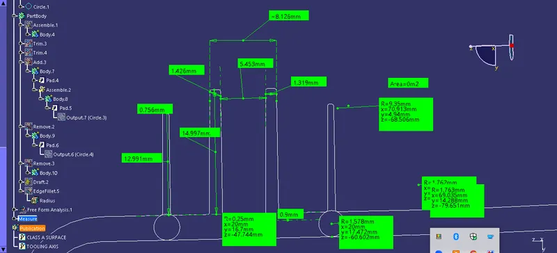
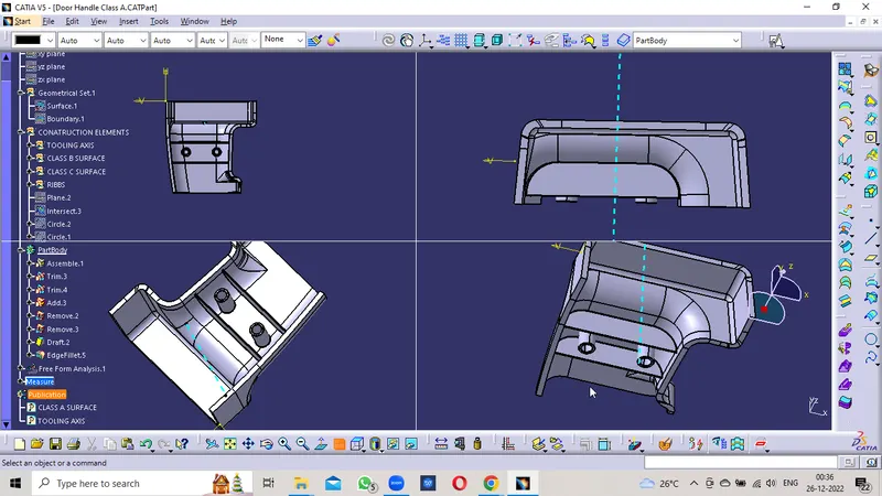
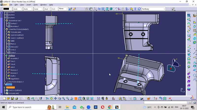
Screenshots of the solid model with the proper color code of the draft angle in various orientations (Isometric, Front, Side, and Top View)
CONCLUSION:
The Design of the Automotive Plastic Component – Door Handle with Ribs & Screw Bosses from Class A is completed using concepts of Draft angle, Draft Analysis for Class A and Final enclosed surface, Tooling Axis creation, and implementation, and Class B and Class C creation.