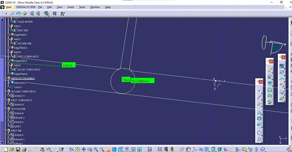
Week 9 - Attachment Feature Creation (Ribs & Screw Boss) - Challenge 1
RIB & SCREW BOSS DESIGN
CLASS A SURFACE
It is the surface which is given to the plastic designer as input.it is the outer most and aesthetic surface.
CLASS B SURFACE
A surface that is at a distance of thickness from class A surface is class B surface.all engineering features are contained in B surface.
CLASS C SURFACE
A surface that joints class A and class B is called C surface.
TOOLING AXIS
- First look at the part in all views and check which is the most appropriate direction for the tool axis.
- For this surface we can see that Y direction is suitable for tool axis since all parts can be seen from Y axis.
- In Y direction we can see that 2 surface will make problem for mold ejection.so we take the intersection between XY plane and part.then extend the line along the surface.then made a dummy tool axis and made more than 3 degree from the extended line by constraining it.
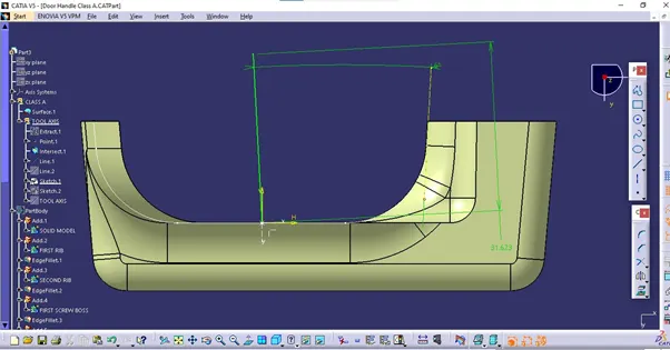
- Then also make another dummy tool axis which is more than 3 degree from other surface.
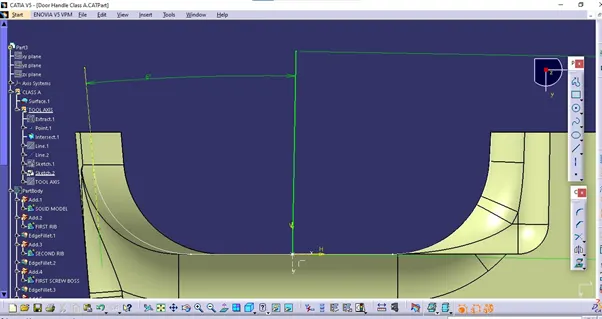
- Then bisect the 2 dummy tool axis and form the orginsl tool axis.
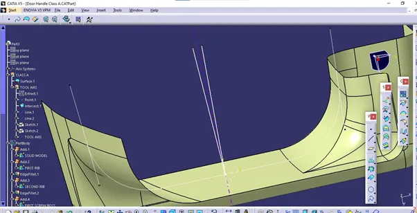
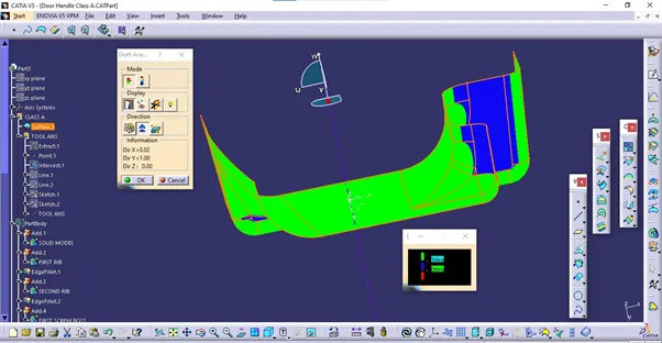
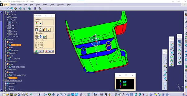
DRAFT ANALYSIS
- Draft analysis is done to check whether the part designed is manufacturable or not.
- Minimum draft angle considered is 3*.
- For analysis goto insert >analysis >feature draft analysis.then place the compass on the tooling axis and click on the part.
DRAFT ANALYSYS ON CLASS A SURFACE
DRAFT ANALYSYS ON SOLID MODEL
RIB &SCREW BOSS DESIGN
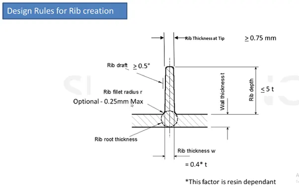
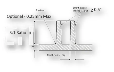
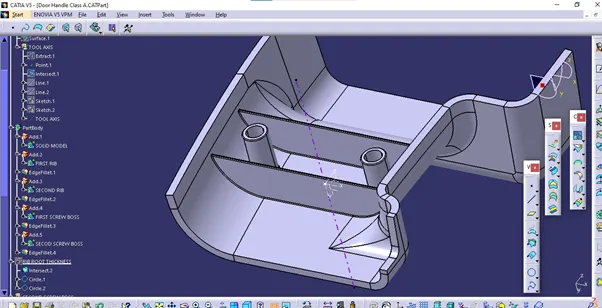
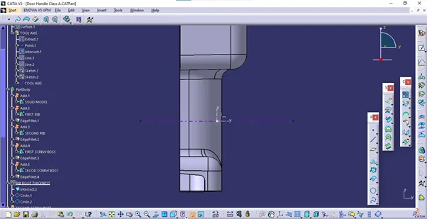
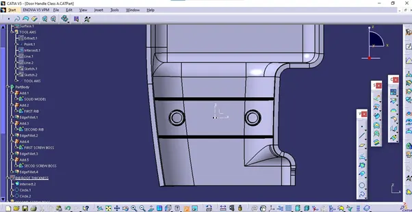
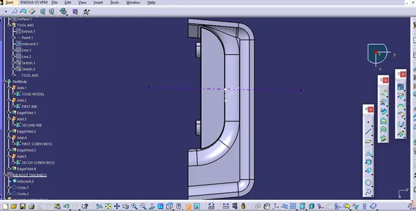
RIB ROOT THICKNESS