Week 9 - Attachment Feature Creation (Ribs & Screw Boss) - Challenge 1
DOOR HANDLE
Tooling Axis creation:
It is defined as the direction in which the mould/core and cavity open. Selection of the direction of the tooling axis depends on the ease at which components can be easily ejected.
By analysing the component the most easily ejectable direction is somewhere close to the Z direction,(might be inclined to it) so we have made a sketch on the YZ plane of Axis System) to create a bisecting line considering the 2 faces which might be difficult to be tooled.
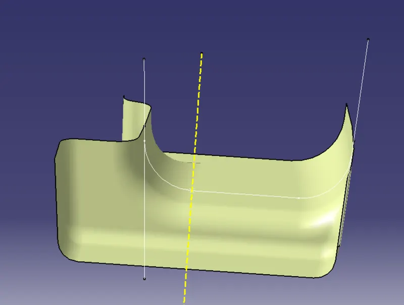
Then resultant tooling axis is created using the bisecting method.
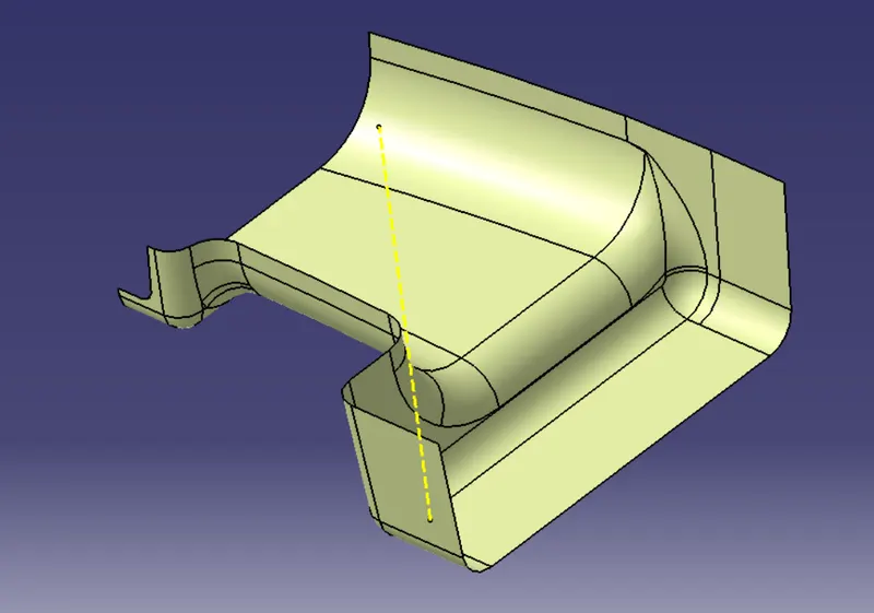
Creation Of Class B surface:

Creation Of Class C surface:
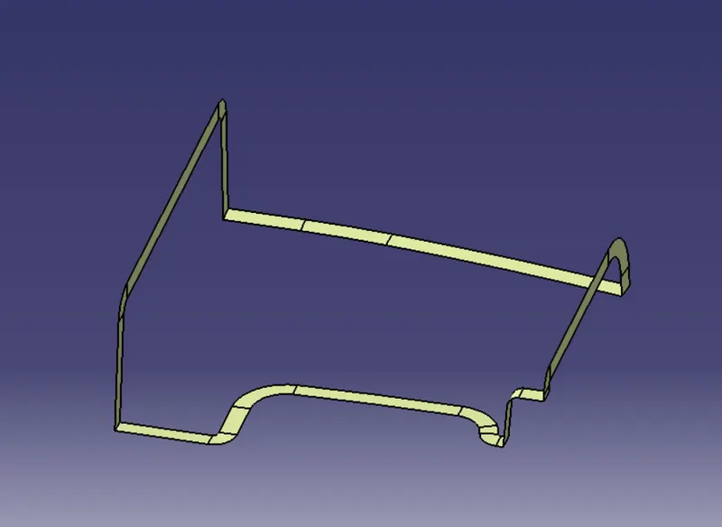
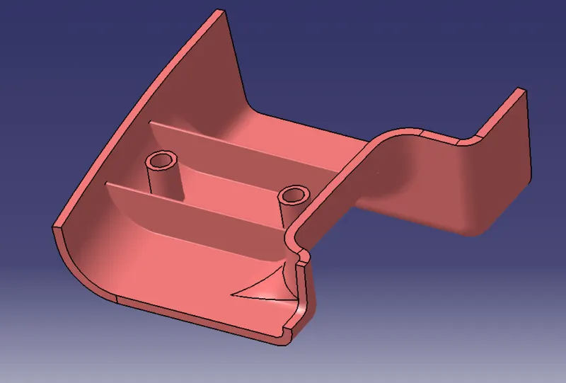
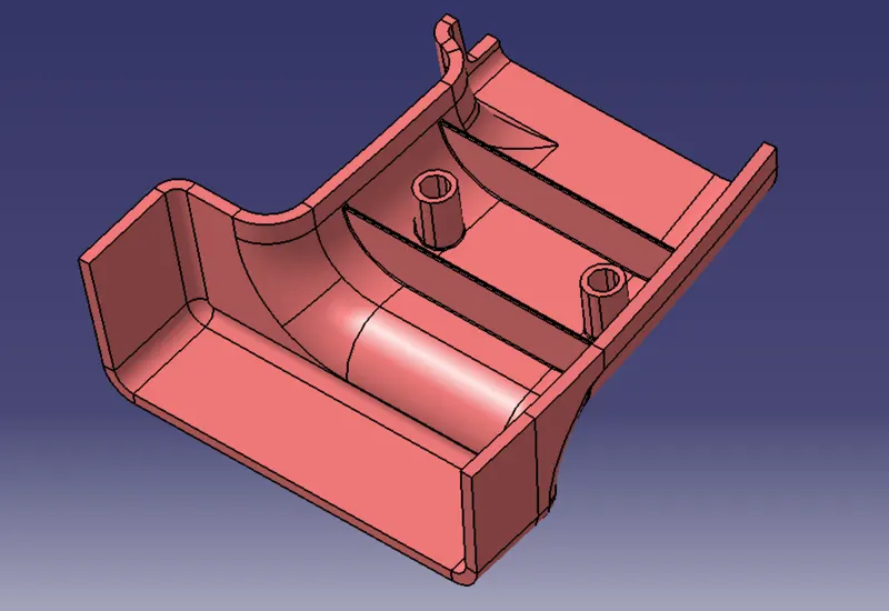
Creation of Door Handle.
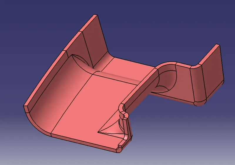
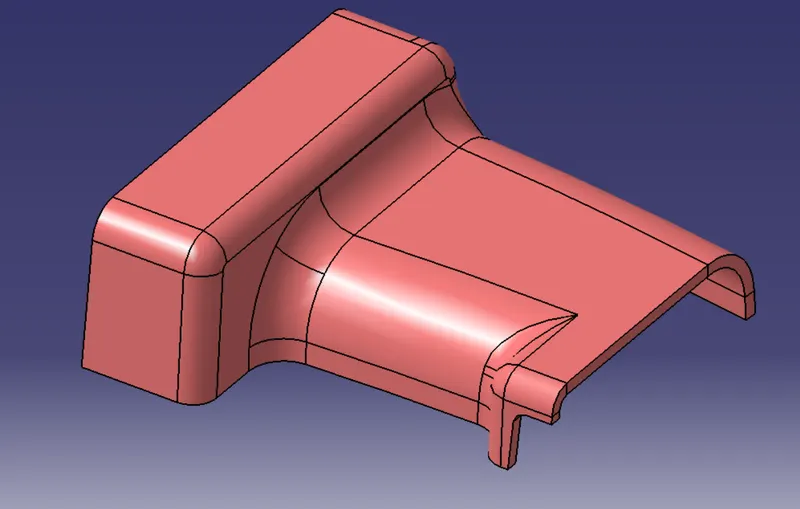
B SIDE FEATURES CREATION
RIB CREATION
- Design Principle for Rib Creation
-
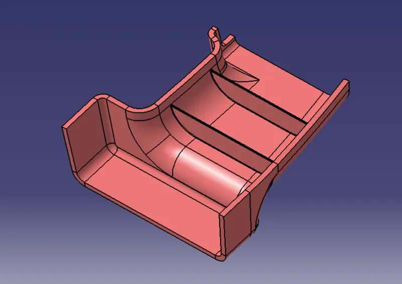
Ribs are thin wall protrusions that extend perpendicularly from a wall or plane. They are usually found in clusters offering support to a plane that would have otherwise been too thick, but can also be stand-alone support for a single wall. They are commonly used to provide additional support and strength to a part. Thickness and location are essential to rib design.
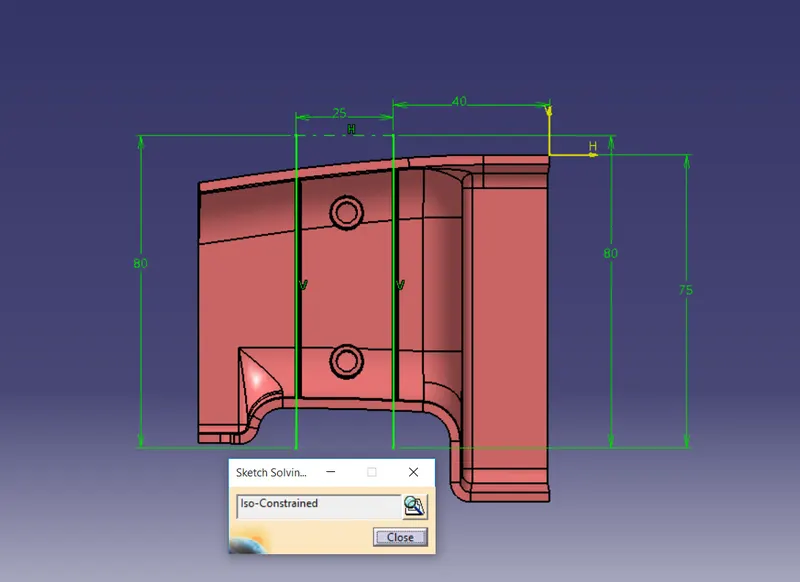
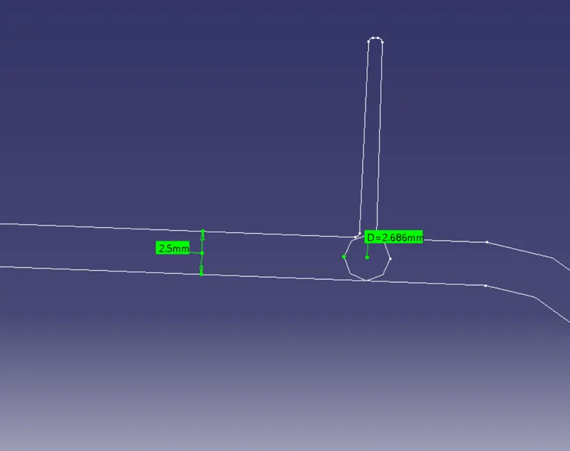
First, the base surface where the rib has to be created is extracted using the Extract command. A positioned sketch is created and the profile for the rib is drawn.
-
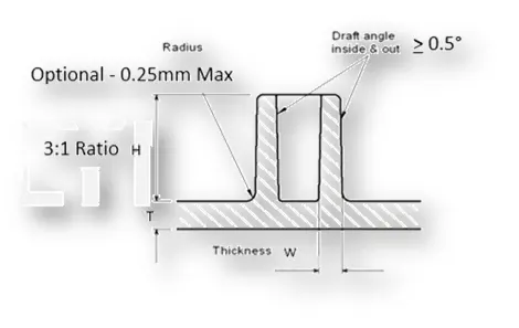
Next, the profile is extruded, to find the height,h=Wall thickness * 5
=2.5*5
= 12.5 mm
Therefore, the height is 12.5 mm
-
The extruded surface is thickened,
Thickness,w=0.4*t
=0.4 2.5
=1mm
Therefore, the thickness of the rib is 1 mm
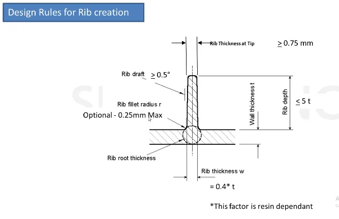
- Sketch Used For Rib Creation
SCREW BOSS DESIGN
- Design Principle for Screw Boss Creation
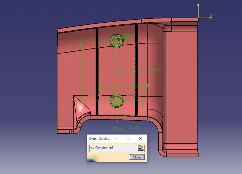
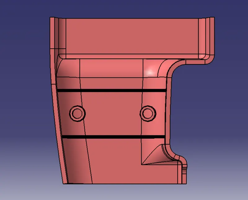
- Sketch Used For Screw Boss Creation
Draft Analysis:
Draft analysis of Class A surafce:
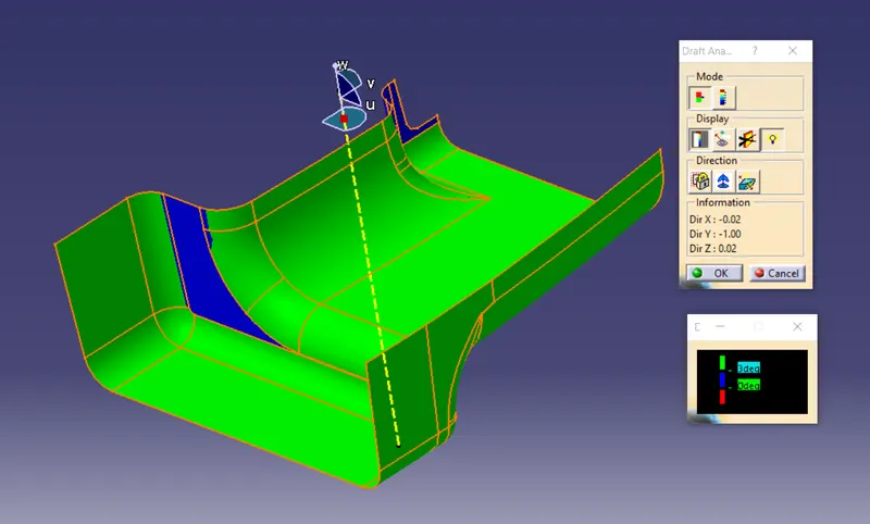
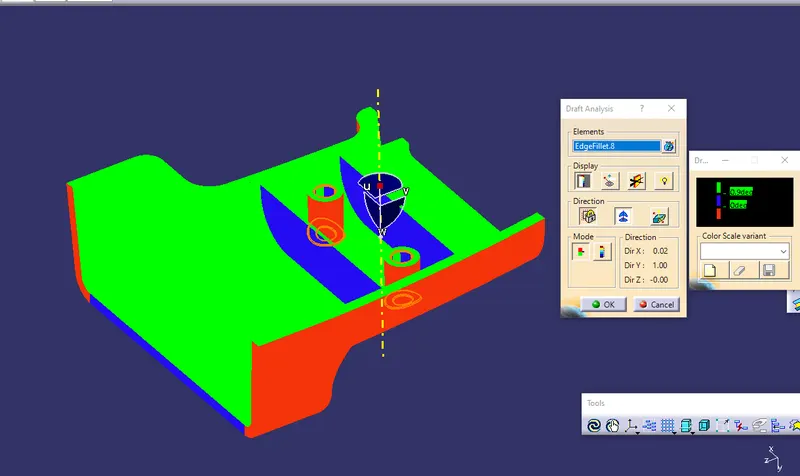
Draft Analysis of Door Handle:
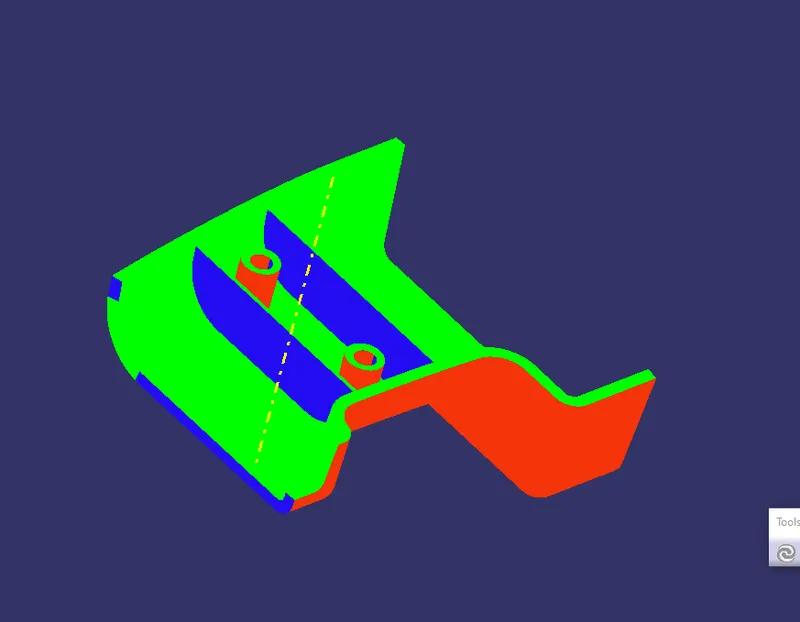
CONCLUSION:
- The Tooling axis and the SolidCAT part with B Side Features is created from the given Class A Surface and Draft Analysis is Performed.