Week 9 - Attachment Feature Creation (Ribs & Screw Boss) - Challenge 1
Ribs and Screw boss
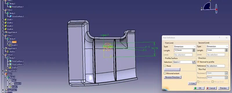
Create the rib for the Drill Handle considering the design rules mentioned in the video.

Create the Screw boss for the Drill Handle considering the design rules mentioned in the video.
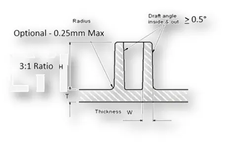
General Guidelines for Bosses:
- Draft - 0.5 degrees on the walls of boss
- Thickness - Typically 40%* of the nominal wall at the base.
- Height to Diameter Ratio - 3:1
- Radii - 0.25mm maximum radii.
OBJECTIVE:-
It's given Class - A surface of Door handle to add 2.5mm thickness and, provide a Ribs and Screw Boss economical stifness and strength in molded parts without increasing overal wall thickness attachment and assembly Ribs and Screw boss
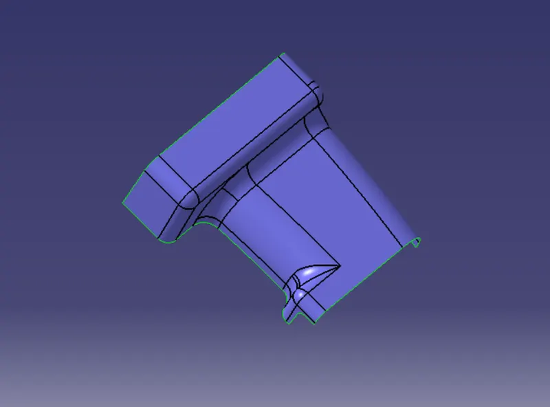
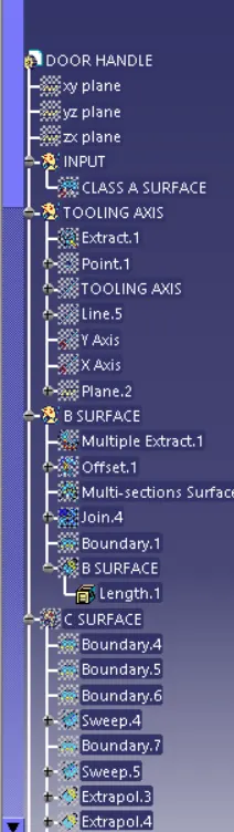
TOOLING AXIS :-
Tooling direction of genrally consider for plan surface of our component ( X,Y,Z) direction or normall to surface
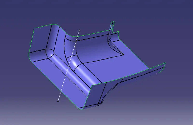
Checking of component draft direction:-
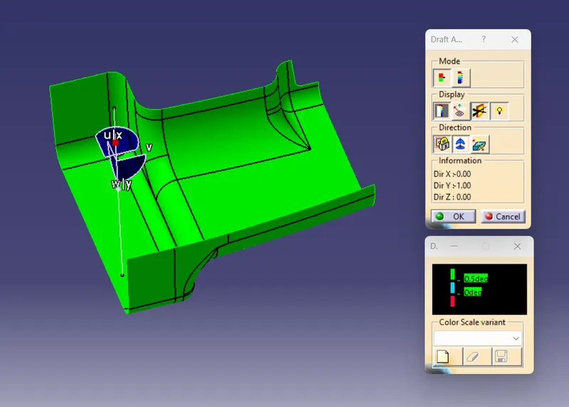
- Drafts is required for on all parts in the direction of mold moment in order to allow parts to release or eject from the mold properly
- Draft is the angle in which the part is tapered to allow it tend to want to shrink to the core side of the mold
- Adding draft help to the part to release . most part or applications required a minimum of 1/2 to 1 degree however 3 degree is widly accepted as the norm
Creation of Class - B surface:-
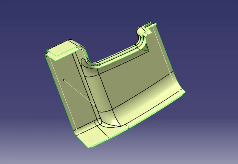
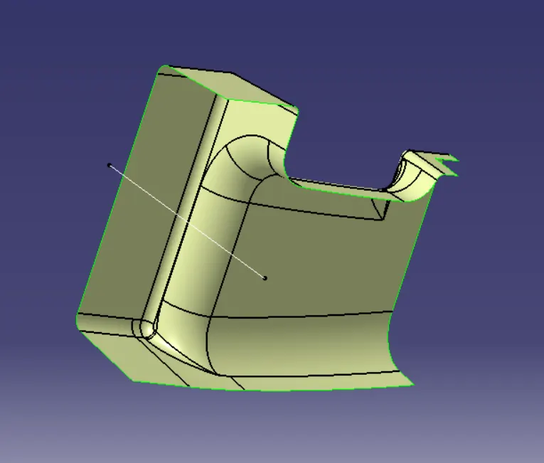
Unhide the Class -a surface and Multiple extracted the Class - A surface and offseting extercted surface and they having some small patches , create the boundary curve and using Multi-section surface and fill it patches
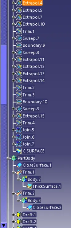
Creation of Class -C Surface:-
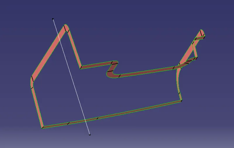
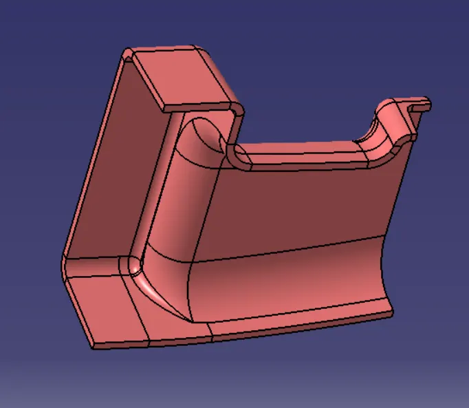
Unhide the class A surface and creat the boundary curve to give reference to surface 90 degree angle to sweep is created and join the A+C= C surface is created
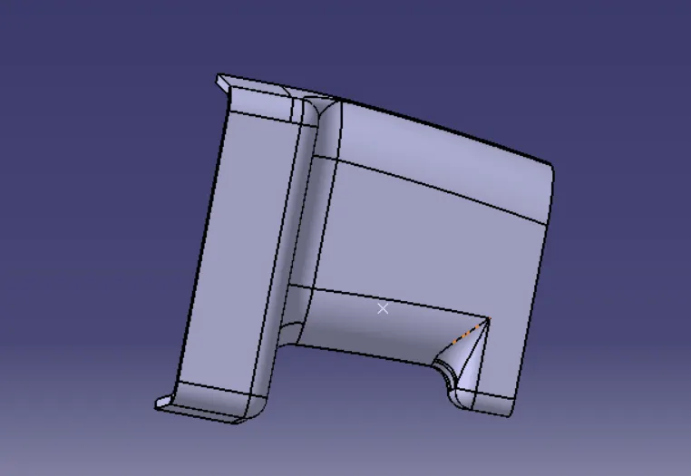
Creation of B side feature:-
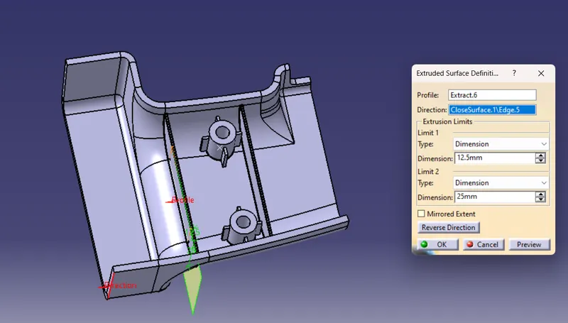
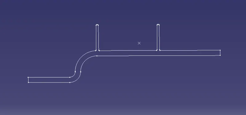
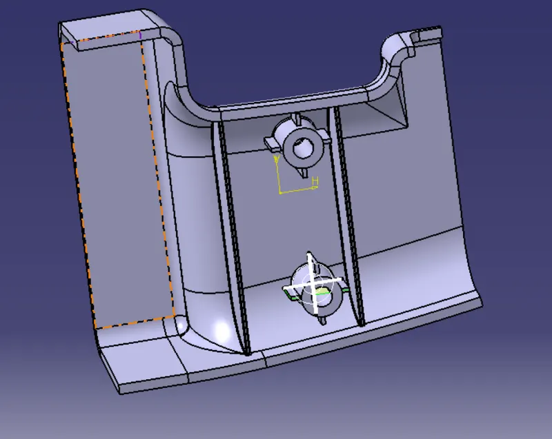
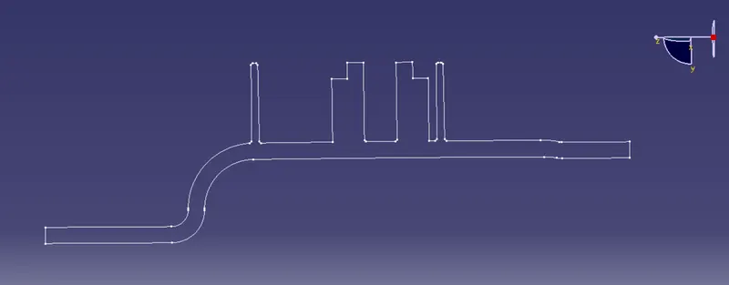
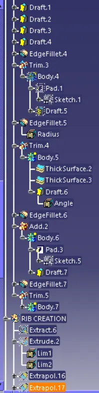
1)RIB DESIGN:-
Ribs are provide a means to economical stifness and strength in molded parts without increasing overall wall thickness
they also faciliate:-
- locating and arresting components of assembly
- providing alginment in mating parts
- acting as stop or guides for mechanism
this section deal with generally guidelines for ribs and parts design
Design rules:-
- Nominal wall thickness of plastic component 3mm
- A deviation of +-30% from the wall thickness is accepted
example:- 3mm thickness
- 2.1 mm is minimum
- 3.9 mm is maximum accepted
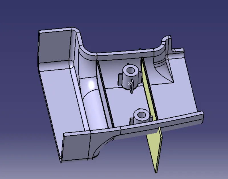
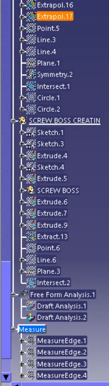
2) Creation of Screw Boss:-
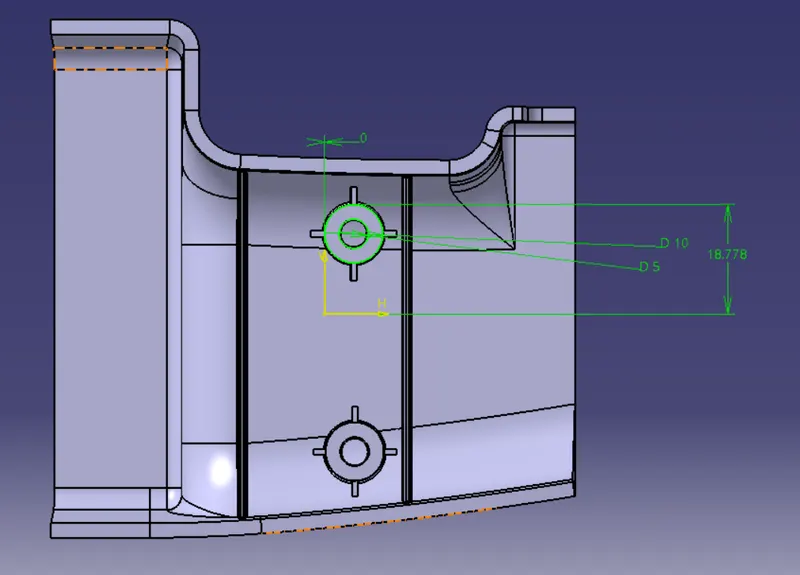
Screw boss find use in many part design as point for attachment and assembly the most common variety consists of cylindrical projections with holes designed to recieved screw ,thread inserts or other types of fastening hardware as a rule of tumb the outside diameter should be remain within 2.0 to 2.4mm times the outside diameter of the screw
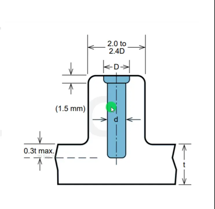
Design rules for screw boss :-
- Draft
- thickness
- height of the diameter ratio
- optional radii
- Boss gussets
- coring and bottom
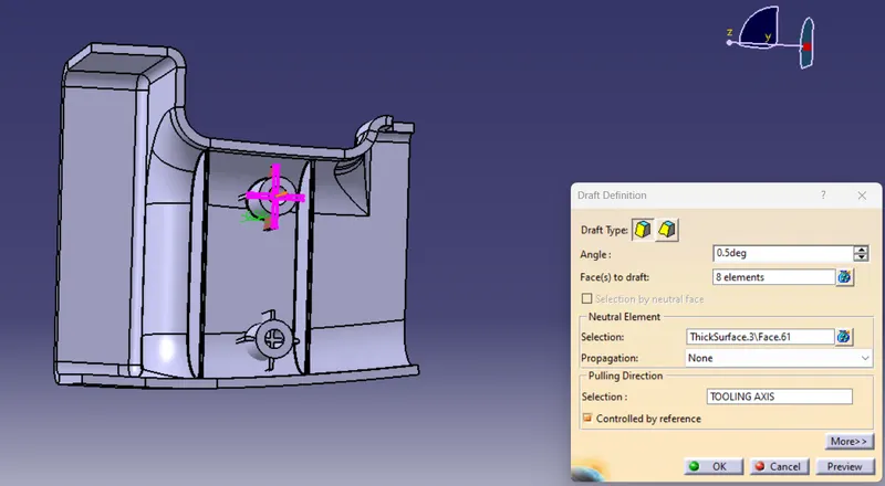
DRAFT ANALYSIS:-
DRAFT ANGLE FOR SOLID WALL PART IS 3 DEGREE AND FOR SREW BOSS AND ROB ITS A 05 DEGREE.FOLLOWING IMAGE SHOWS THAT OUR SOLID BODY IS IS CORRECT AND FORMABLE ALSO BECAUSE IT PASSES THE DRAFT ANALYSIS.
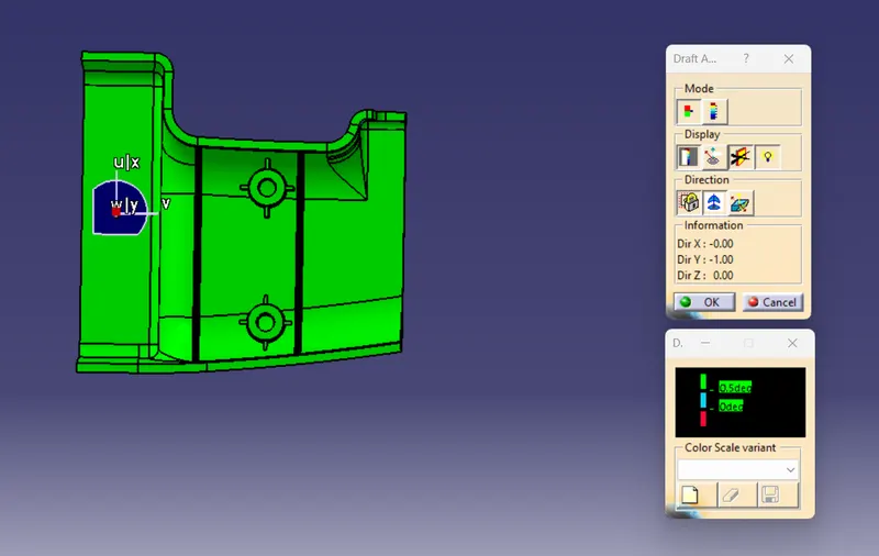
Conclusion:- mould Flow without shrinkage of parts