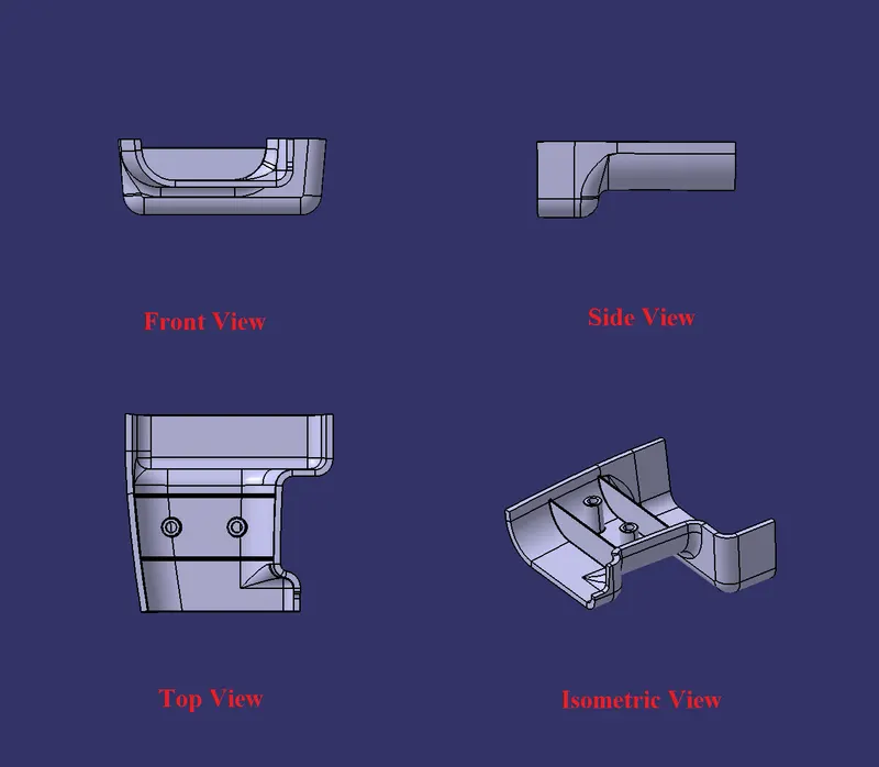
Week 9 - Attachment Feature Creation (Ribs & Screw Boss) - Challenge 1
Given CLASS A SURFACE
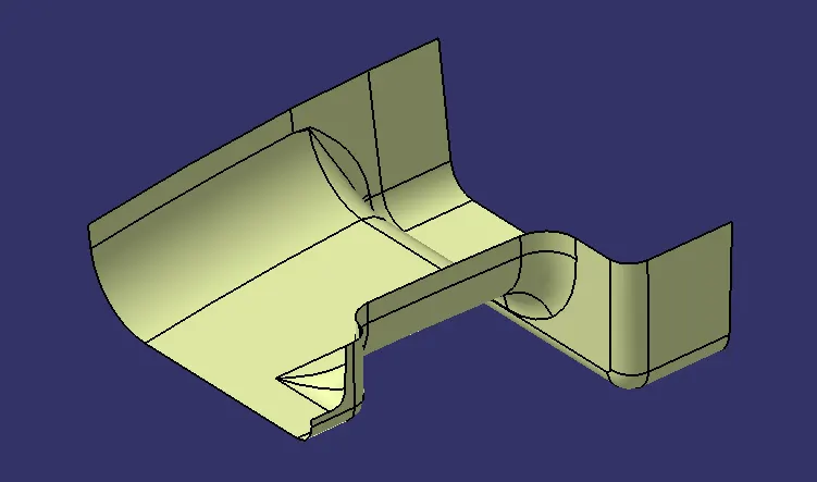
The Way of Creating the Tooling Axis
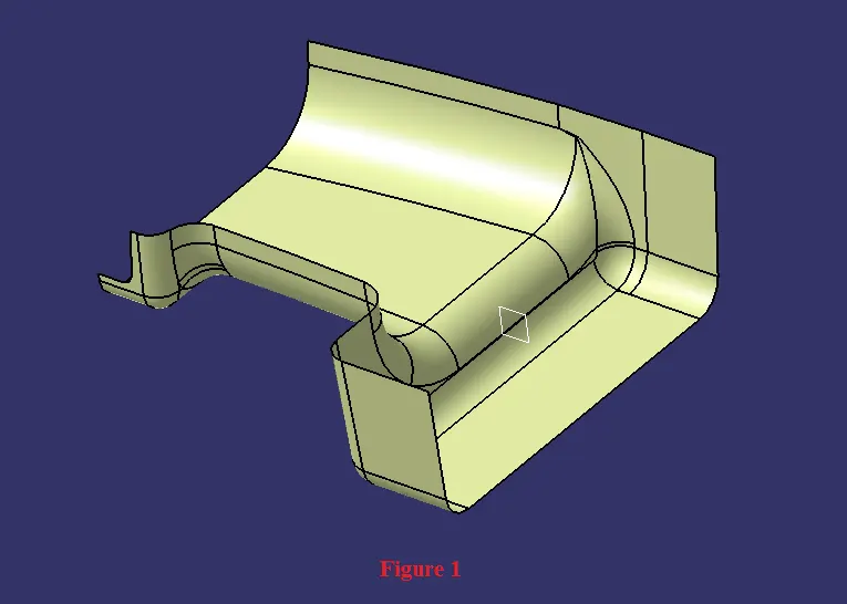
Need to take center of the surface for a Tooling axis. So, here i took horizontal line which is easy to make a plane at surface with the help of Plane command(Plane Definition = curve + point(default = middle) plane) as shown in figure 1.
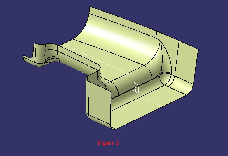
Then i created intersect line on surface by using that plane with the help of intersect commmand(intersect definition = surface + plane) as shown in figure 2.
By the uses of the intersect line i created plane with the help of Plane command(Plane Definition = curve + point(default = middle) plane) as shown in figure 3.
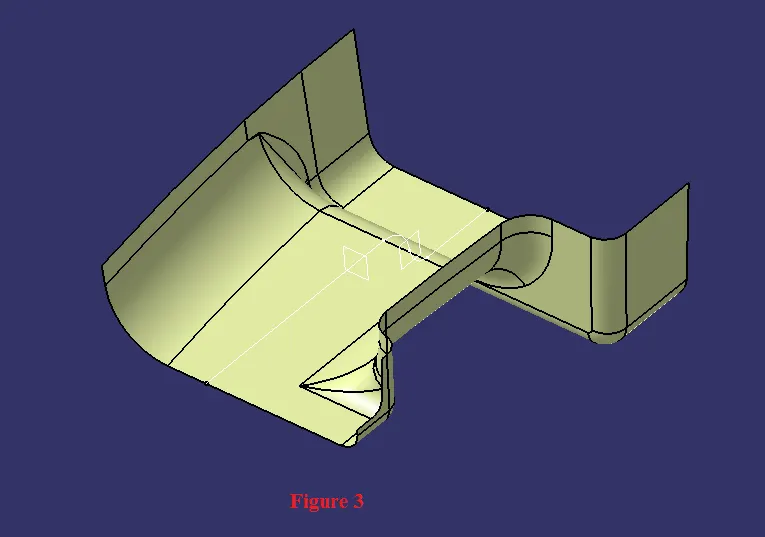
Then i created intersect line on surface by using that plane with the help of intersect commmand(intersect definition = surface + plane) as shown in figure 4.
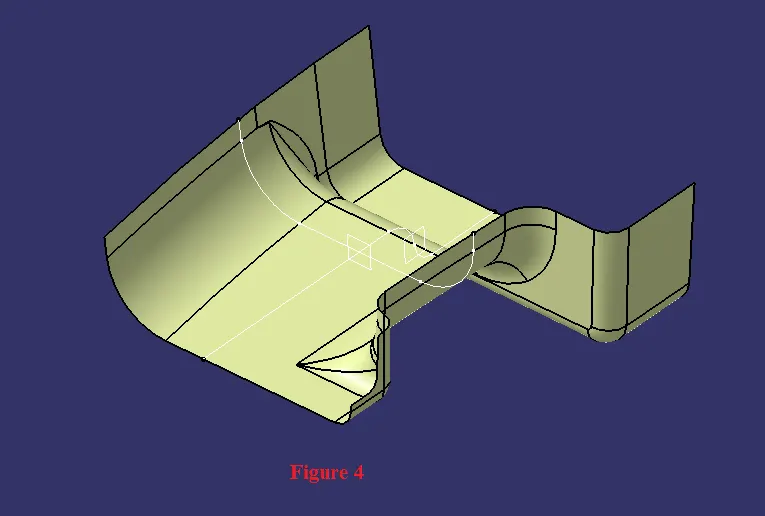
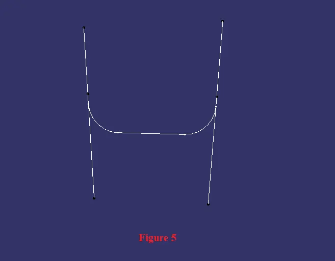
Then i created a line on each side of the inclined line with the help of line command(line definition = point to point) as shown in firgure 5.
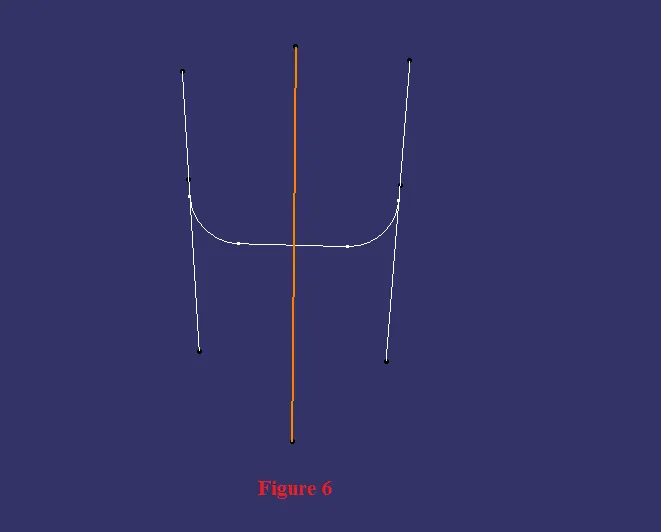
By the uses of two line i created a bisecting line which is showing in orange color with the help of line command(line definition = bisecting = line 1(bisecting line) & line 2(line which is created by surface + point)). as shown in figure 6.
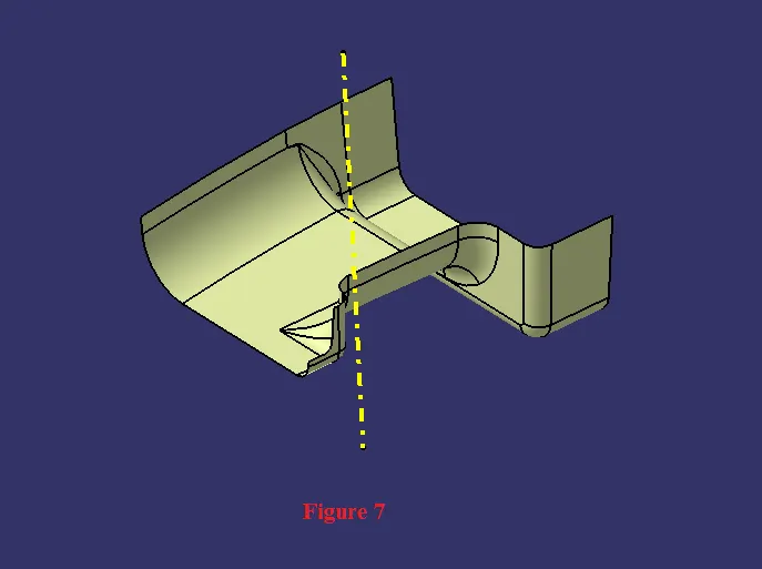
Thus the way i created Tooling Axis for draft analysis as shown in figure 7 which is showing in yellow color center line.
Tooling Axis
Draft Analysis
Draft Analysis is used to analyze whether our part model created in CAD is manufacturable based on the draft condition applied.
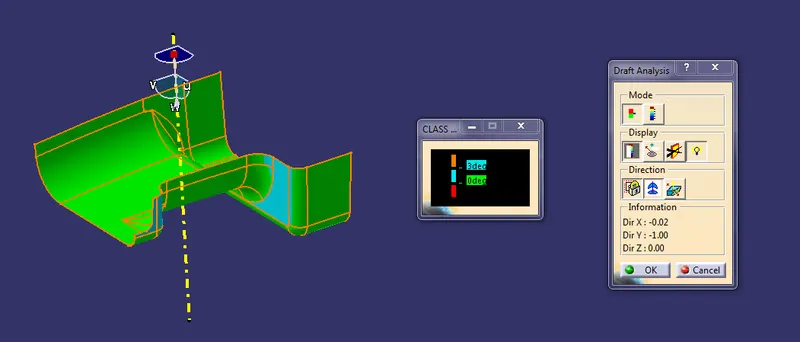
CLASS A SURFACE
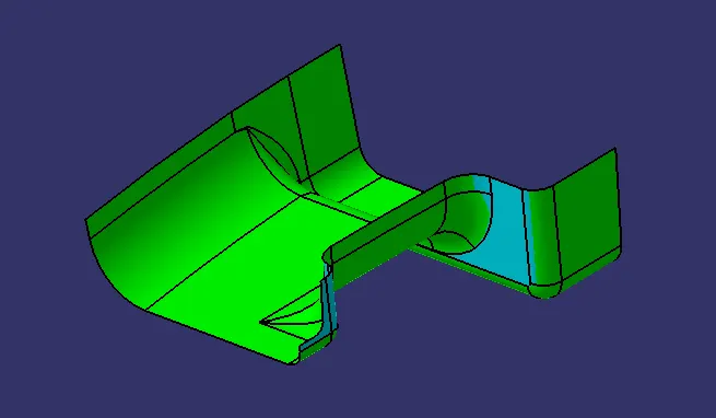
Solid model with the proper color code of the draft angle
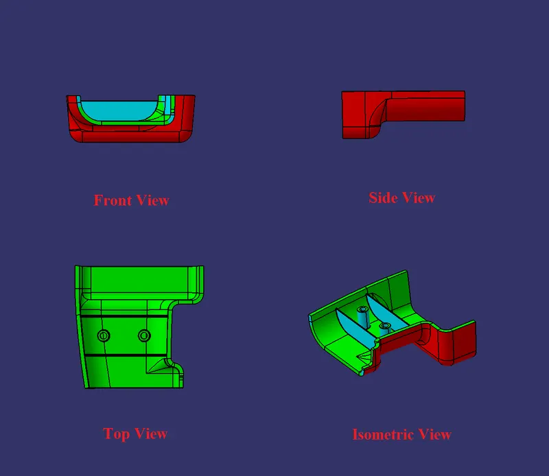
Door Handle in various orientations