Week 9 - Attachment Feature Creation (Ribs & Screw Boss) - Challenge 1
Attachment Feature Creation
Aim
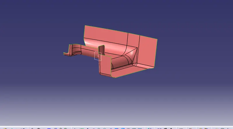
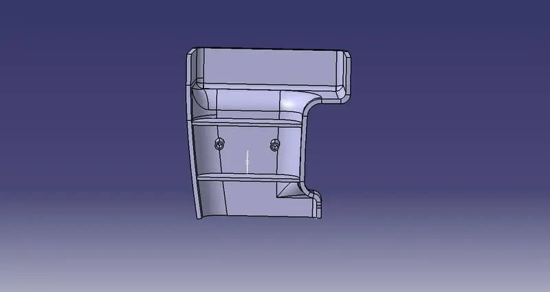
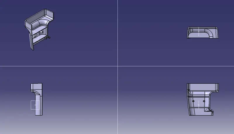
To create the door handle components ribs and screw boss from the given Class A surface.
To create the tooling axis for the given Class A surface to meet the requirements.
To attach the b-side feature in the component.
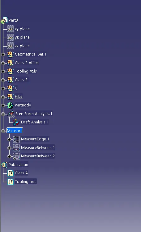
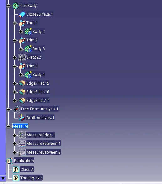
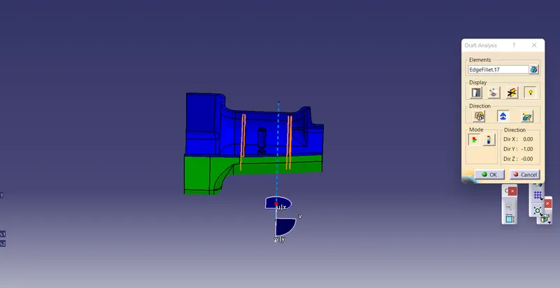
To perform the draft analysis on the model.
Tools Used.
- Boundary
- Join
- Multiple extracts
- Trim
- Surface offset
- Draft analysis
- Draft
- Edge fillet
- Surface sweep
CREATING THE RIB
Ribs are thin-walled protrusions that extend perpendicular to a world or pain. They are usually found in clusters offering support to a plane that would have otherwise been too thick but can also be stand-alone support. For a single-word twist, they are commonly used to provide additional support and strength to apart. Thickness and location are essential to rib design.
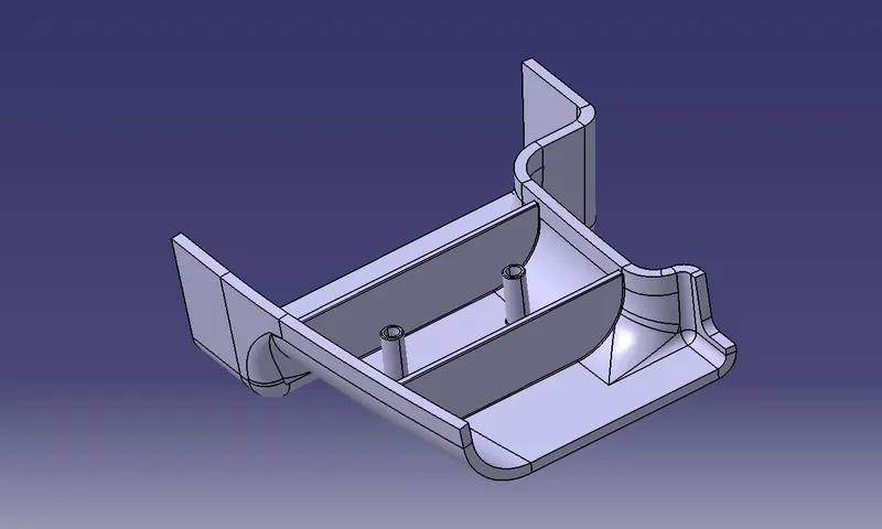
Pause. The best surface where the ribs have to be created is extracted using the extract comments from a positioned sketch is created and the profile for the rib is drawn.
Next, the profile is extruded to find the height h= Wall thickness*5
So Height =2.5*5=12.5
The extruded surface is thickened
Thickness= W= 0.4*t
0.4*2.5= 1 mm
The draft is applied on the sides of the rib. As per the design rule, the ideal draft angle is 0.5
Deg, Then fillet is applied on the faces of the ribs, as per the design rules the fillet can be 0.25mm
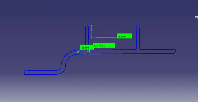
Now we have to check the rib root thickness.
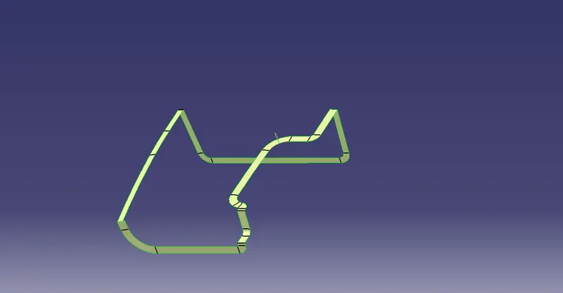
To check for the rib root thickness, we have to take an intersection with the desired plane and the part body. Once we get to the intersection, we have to create a try tangent circle at the rib area and measure it. The value must be within 30 percent greater of the wall thickness.
After all these works
Creating the screw boss
Screw Bose features are commonly found in injection models missing. They are used to aid in the assembly of motor parts by providing a channel for a screw their primary use is to strengthen holds or slots in the surface present in the part model.
Design Rules for creating screw boss
Thickness
Draft
Boss Gusset
Fillet
The construction process of creating the screw Boss is explained below.
Thickness W= 0.6*T
0.6*2.5= 1.5mm
Once the sketch is completed then it's padded using the pad command, and the height-to-diameter ratio can be 3:1, The draft is given as 0.5 degrees as per the design rules. After that fillet is applied on the faces of the screw boss.
After the creation of the components, analysis the height width etc of the ribs, and draft analysis of the whole component