Week 9 - Attachment Feature Creation (Ribs & Screw Boss) - Challenge 1
Aim :
To create the Rib for the drill handle considering the design rules for rib creation and Screw boss creation and then perform the Draft analysis for the final component.
Objective :
- Create the Tooling axis by using the bisecting method.
- Design the class-B and class-C surfaces and join them.
- Create the solid feature by surfaces we create.
- Design the required Ribs and Screw Boss and analysis them.
- Perform the Draft analysis for the final component
METARIAL SELECTION:
- ABS
WHY THIS MATERIAL IS USED:
- ABS has a low melting point which enable its easy use in the injection moulding process and 3D printing .It also has high tensile strength and is very resistance to physical impacts and chemical corrosion,which allow the finished plastic to withstand heavy use and adverse environmental condition.
- High dimensional stability (mechanically strong and stable over time).
- High surface brightness and excellent surface aspect.
Ribs:
Attachment features , b-side features,engineering features all are same
- RIB DESIGN RULES;
- T-norminal wall thickness
- A: base width od a rib : 0.3-0.7T
- B: base height=less than 5T
- c:spacing between ribs:more than 4T
- D: RADIUS AT LEASE OF RIBS:T/8 or 2.5mm
- E: draft of ribs :0.5degree-2degree
- ribs root thickness should less than :0.4T
They are vertical thin walled features provided inside of the component mostly on the B-surface. It is mostly located in the areas where it is not visible to naked eye.
Ribs are provided in a plastic component where it may be weak or load is acted.
They provide strength,rigidity to the part and support to other features like boss.Ribs are provided instead in areas to avoid thick walls to avoid plastic defects like sink marks,warps and voids.
They help to locate and arrest components of an assembly,provide alignment and also act as stops or guides for mechanisms.
Draft of Rib :
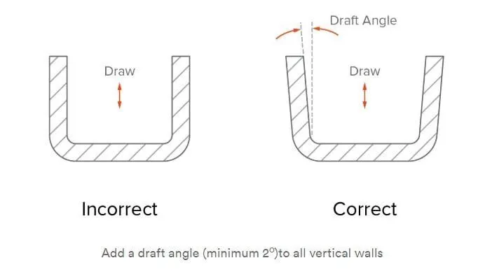
The draft for a rib should be 0.5 degree which enables the thin walled feature to eject during molding.It cannot be more than 0.5 degree, as the tip will become very small and cannot be moulded.
Rib Thickness of Rib :
The Rib thickness of the component can be 40% or 0.4 times the Wall thickness of the component. It is maintained like that because if the rib thickness is more it will cause sink marks or take more time to cool than the wall thickness which is not ideal for moulding.
Rib Thickness at tip of Rib :
The rib thickness at tip after draft should be greater than or equal to 0.75mm. If it is less than 0.75mm, then the rib will become thin and it will be difficult to fill and eject the component.
Fillet of Rib :
The Fillet of Rib should be 0.25mm maximum.It should not be more than 40% of the Rib root thickness. Fillet helps to avoid sharp corners and avoid stress.
Depth or Height of Rib :
The depth of Rib is usually maintained 5 times the wall thickness. It cannot be more than this as it will create a sharp edge after the draft. This may sometimes vary based on other conditions.
Gap between Ribs :
The distance between ribs is maintained in the ratio of 3:1. That is the height of the rib divided by 3 which should be the minimum distance between ribs. This distance prevents the formation of thin walls which leads to cracking.
CLASS A SURFACE:
Checking of A-surface :
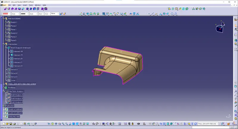
The Drill handle A surface given as input was checked for any issues in the surface and it was confirmed by taking a boundary of the surface.
Since, there was no boundary created apart from the outer edges, the surface was determined to be fine.
Tooling Axis :
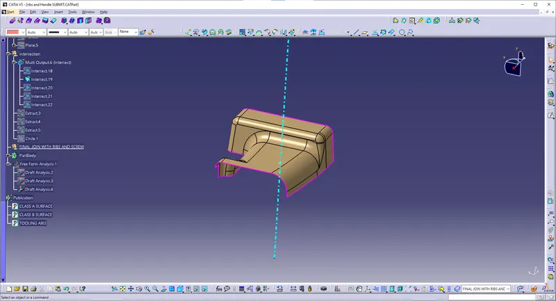
Class-A surface is first analyzed to create the tooling axis or tooling direction that molds pull apart in injection molding. Tooling direction is important for plastic product design as it decides the direction for mold separation.
Step followed for the creation of tooling axis :
- Reference point is first created on the extracted surface.
- New axis system is deployed to plot clearance lines.
- The X-direction and Y-direction along the class-A were used to create the tooling axis.
- Graphic properties of the tooling axis were changed before publishing.
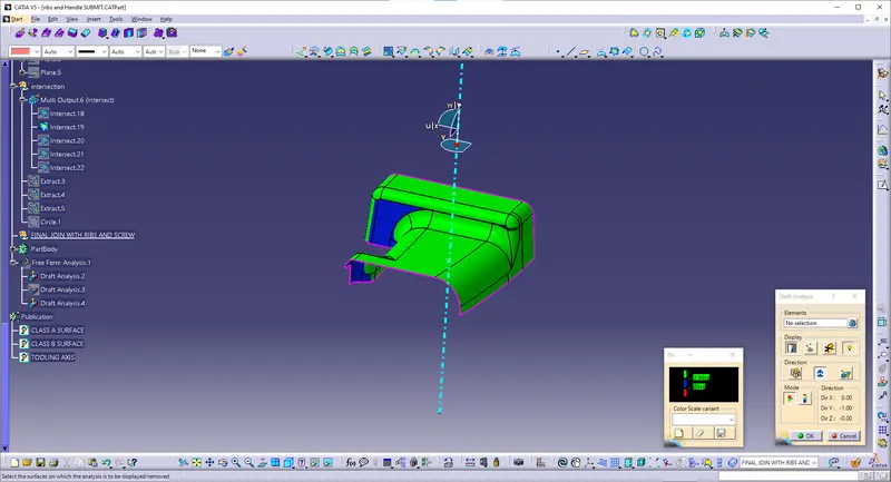
Draft analysis of A surface:
The draft analysis of the A surface is carried out based on the tooling axis with a draft of 3 degrees.
It is found that few surface are in red and needs to be corrected by the styling team. Based on the current surface,It was decided to proceed with the Part design
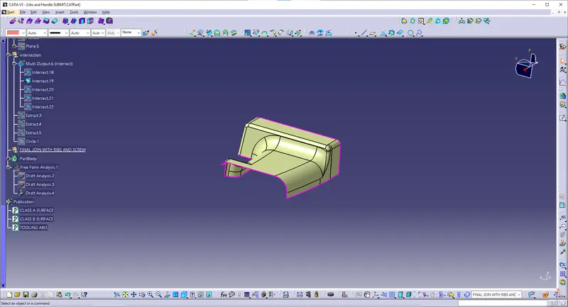
Creation of B surface:
The B surface was created by offsetting the A surface by 2.50mm. A
Multi-section surface was created in one area where the offset was not done.
The final joined surface was checked for any other issues using boundary
Command. Thus the B surface was created.
Creation of C surface:
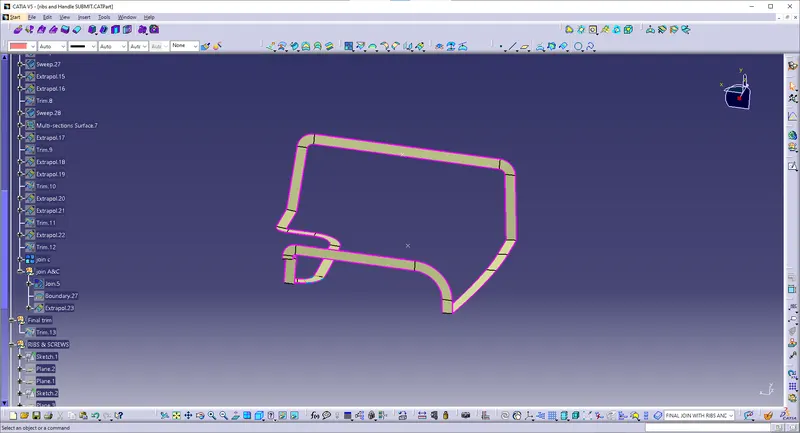
After the B surface is created, The C surface or the thickness is created based on the tooling axis or the A surface. It is done using sweeps and multi-section options.
It is joined and trimmed to form a single C surface
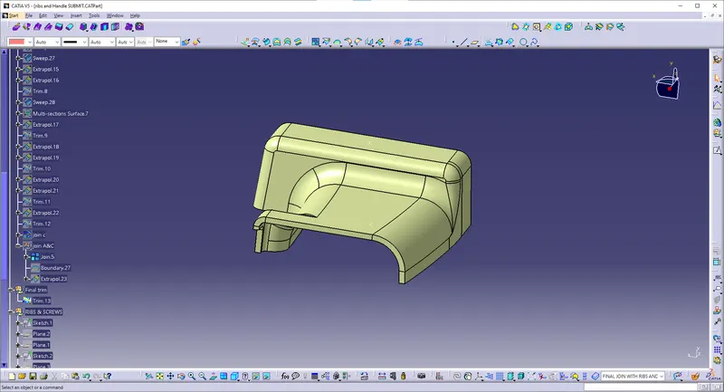
JOIN A & c surface:
Creation of Closed body :
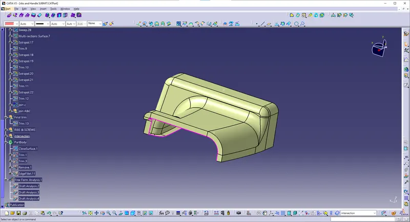
All the A,B and C surfaces are trimmed or joined together to form a closed surface body and using volume it is made a solid body. It should be checked that there is no gap in the closed surface or solid body cannot be created.
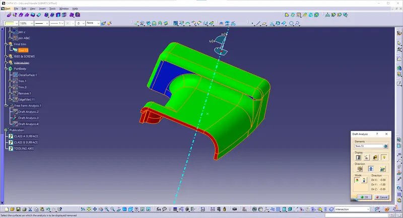
DRAFT ANALYSIS FOR CLOSED BODY
Creation of Rib and Rib root thickness analysis
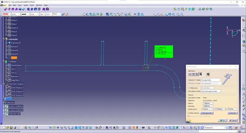
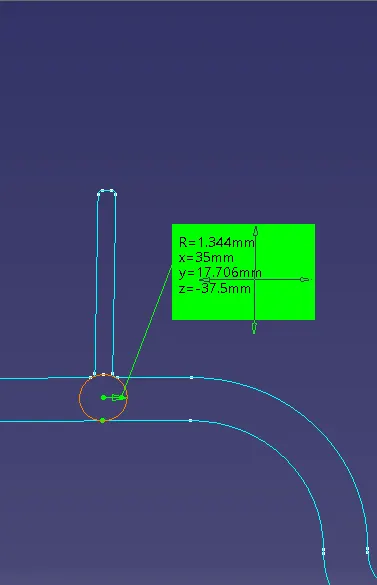
Two Ribs were designed following the design guidelines mentioned above and created on the B surface. To check , if the Ribs adhere to the guidelines, an analysis was done by taking an intersection with the rib. (See Image 9)
The ribs created were determined to be within the design specifications.
Two ribs were spaced using the 3:1 ratio.
The ribs are trimmed with the solid body , draft and fillets are given.
SKETCH OF RIBS
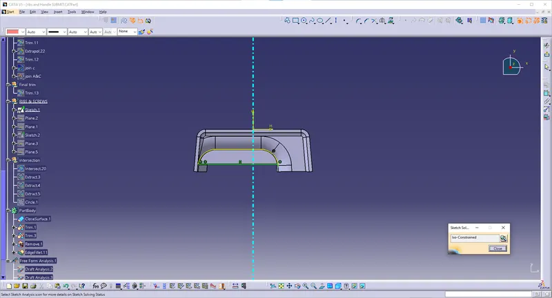
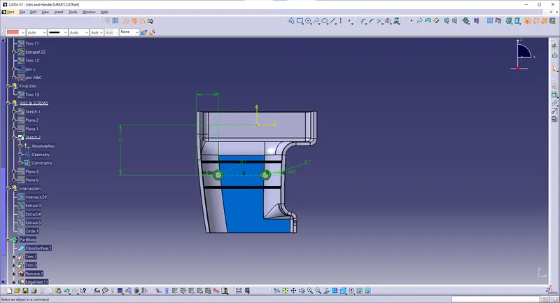
SKETCH OF SCREW:
SCREW Bosses :
- DESIGN RULE :
- Outer diameter of the screw boss should be 2.0-2.4times the outer diameter of the screw
- T-NOMINAL THICKNESS:
- it less tha or equal to 5T of height in ribs
- it more than height in 5T is short shot
- Depression its happens on the class A surface is called sink marks
The bosses are projections given on the B surface and are the point of attachments of two plastic parts. The bosses are designed so that screws,inserts can be threaded in it.
Bosses need to be connected to walls using ribs instead of merging it as it will create more thickness in those areas.It needs to be positioned away from the walls preferably.
CALCULATION OF SCREW BOSSES:
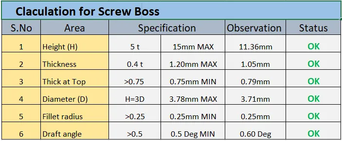
Diameter of Boss :
The boss outer diameter is 2-2.4 times the diameter of the hole diameter. The depth of the hole of the boss
depth of hole in Boss :
The depth of the hole in the boss should be more than 30 % inside the wall thickness.
The depth cannot be too small or large as it will create issues like sink marks or very thin walled areas.
Thickness of Boss :
The thickness of the Boss should be 60% of wall thickness per side. If the boss is thicker, it will lead to more heat to be retained and ultimately to more sinkage in those areas.
Radius of Boss :
The Fillet of the boss should be 0.25mm maximum.It should not be more than 40% of the wall thickness . Fillet helps to avoid sharp corners and avoid stress.
Height of Boss :
The height of the boss should be in the 3:1 ratio. The height must be 3 times the wall thickness of the component.
Draft angle of Boss :
The draft angle of 0.5 degrees as in ribs are used in the boss for smooth ejection of the component.
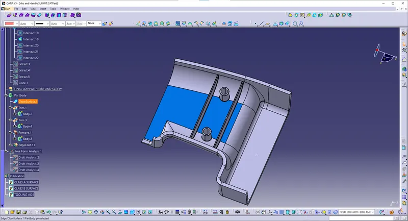
Using the above design guideline, two bosses were designed for the Drill handle.
Creation of Bosses for Drill Handle :
Two bosses were created by using the sketch and pad commands. The hole was considered for M6 taps with diameter of 5.2 mm and outer diameter of
9.2 mm ( 60 % of thickness per side).
The depth of hole is maintained at 12.00 mm and the draft angle is 0.5 degrees.
The bosses are union- trimmed with a closed body and filled with a radius of 0.25mm.
The following image shows the creation of Bosses.
Draft analysis of the component and attachment features :
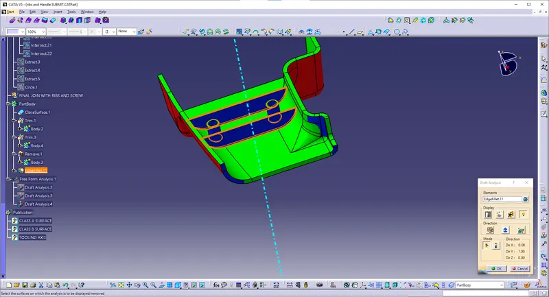
The overall draft angle of 3 degrees is used to check the component for draft analysis.
The areas mentioned earlier in the A surface and few vertical walls were within the limit but even considering those areas , the given draft was sufficient for part ejection
PART BODY SURFACE:
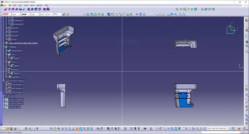
FOUR VIEW OF SURFACE:
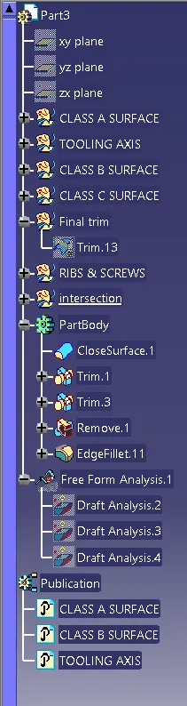
FAMILY TREE :
Conclusion :
The attachment features like Ribs and bosses were created by following the design guidelines on the drill handle component.