Week 9 - Attachment Feature Creation (Ribs & Screw Boss) - Challenge 1
Aim:
To Create the rib for the Drill Handle considering the design rules.
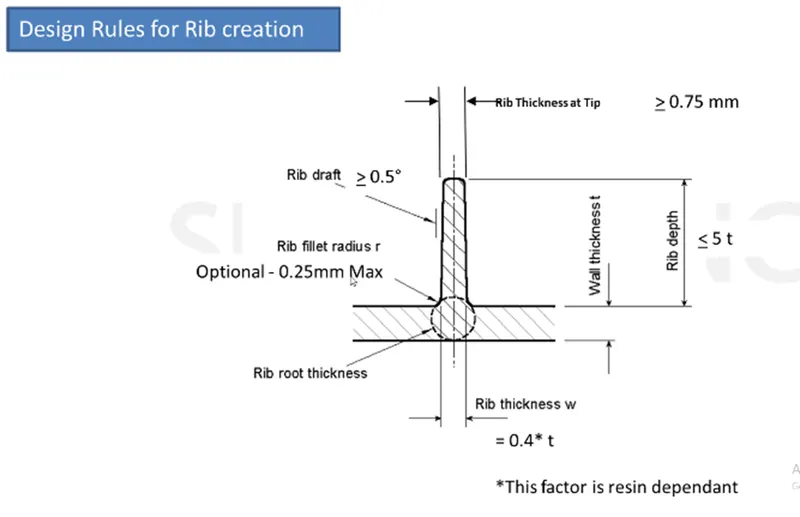
RIBS-
Ribs are indispensable functional structures on many plastic parts. It can effectively improve the rigidity and strength of plastic parts like the H beam. Ribs are generally designed on the non-appearing surface of the plastic part, and its direction is as close as possible to the flow direction of plastic melt filling. Ribs should neither be too long nor too thick, otherwise, it will increase the difficulty of injection moulding, causing problems such as voids and sink marks on the back.
BOSS-
Bosses are common structures on plastic parts in home appliances and interior and exterior of auto-mobiles, mainly for positioning and fastening. The base of bosses often cause sink marks on the back surface of a part, this is because of the large wall thickness. The solution is to core out some material at the base.
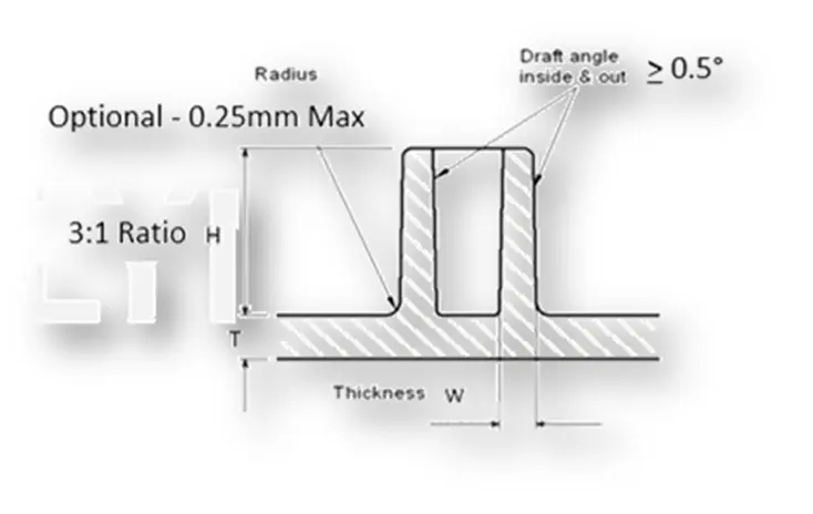
- Draft - 0.5 degrees on the walls of boss
- Thickness - Typically 40%* of the nominal wall at the base.
- Height to Diameter Ratio - 3:1
- Radii - 0.25mm maximum radii.
Given Class A Surface-
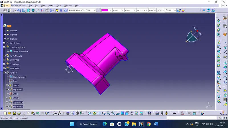
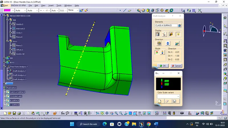
class a draft
Class B Surface Creation-
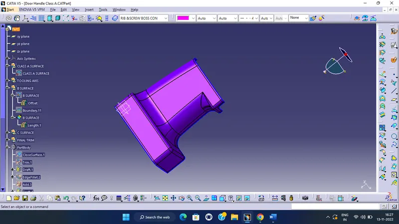
To create class B surface offset the class A with proper direction and distance. Here distance is the thickness of the component. As no given thickness is provided, so we are assuming the thickness value is 2.5MM. Result after offsetting-
Class C Surface Creation-
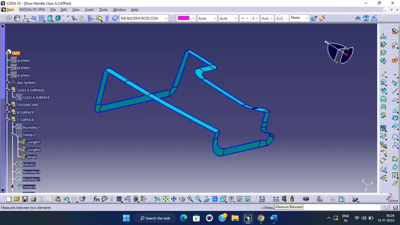
To create class C surface create boundary using class A surface boundary with 'Boundary' command in 5 parts. And use 'Sweep' command to create a surface that is in 90 deg. angle with class A surface. The reasulyent surface will be the class C surface.
Final Closed Surface-
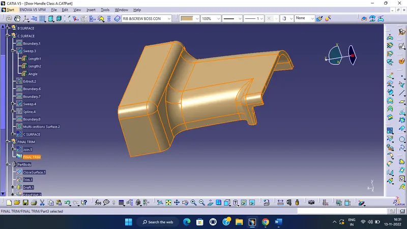
Class C surface trimmed with class B surface properly and joined with class A.
Solid Body-
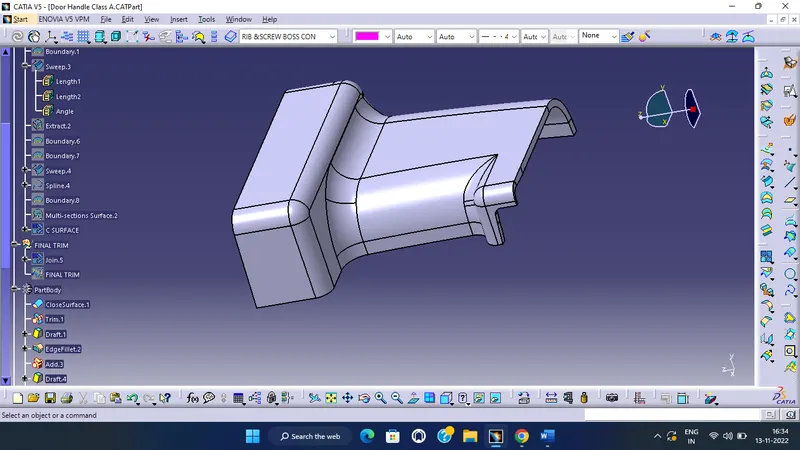
Using 'Closed Surface' command of Part Workbench we have to make make the body solid.
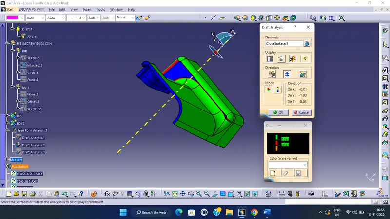
Analysisnlysis :
- The part created has to be changed to the material modes in the display frame.
- Compass is enabled and aligned along with the tooling direction.
- Lock command is then applied to fix compass along with tooling axis.
- Color codes are classified and Draft angle is applied.
- Running point analysis is used to display permissible draft angles.
RIBS-
As per design standerds we will create a sketch where ribs are needed.
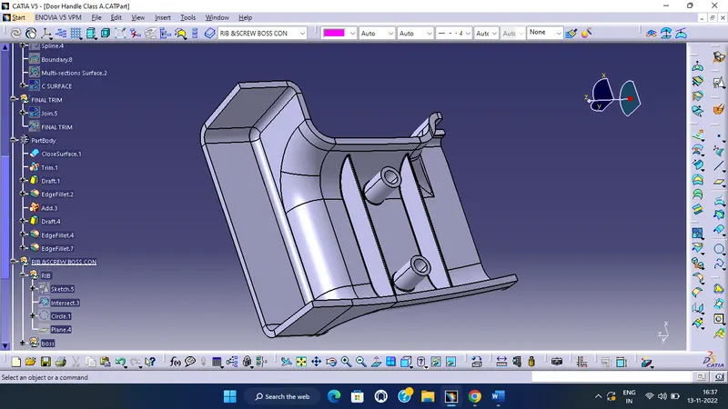
Extrude those line upto the 5 times the base thickness that is 15MM, but we are taking here 12MM. Then using 'thicken' command thicken that part 1.2MM as per design standerd(0.4*Base thickness(3MM)). Then give draft for both wall with nutraf surface(Class B) of minimum 0.5 degree. We can give draft more than that, but tip thickness should not less than 0.75MM. After that give fillet of all surface with fillet value 0.25MM. Now ribs are almost done.
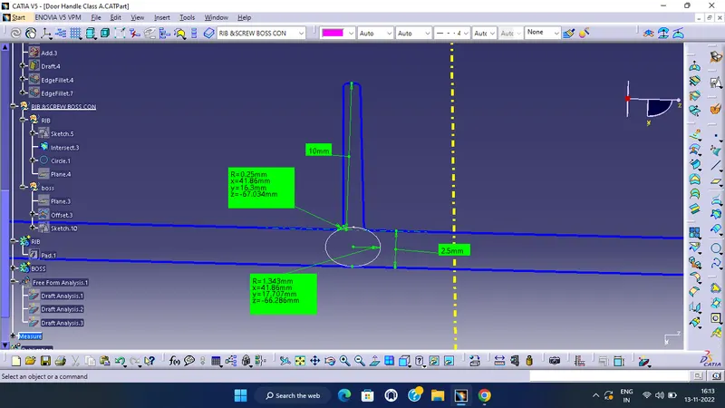
SCREW BOSS-
We are considering a M6 screw to design the screw boss. So we will create a sketch of two 5.2MM inner dia circle. And will 'Pad' those with 3:1 height and base thickness ratio, where thickness of boss wall will be 0.6 times base thickness. Also have to give draft of minimum 0.5 degree with nutral surface of class B. Lastly give fillets of 0.25MM.
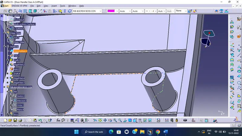
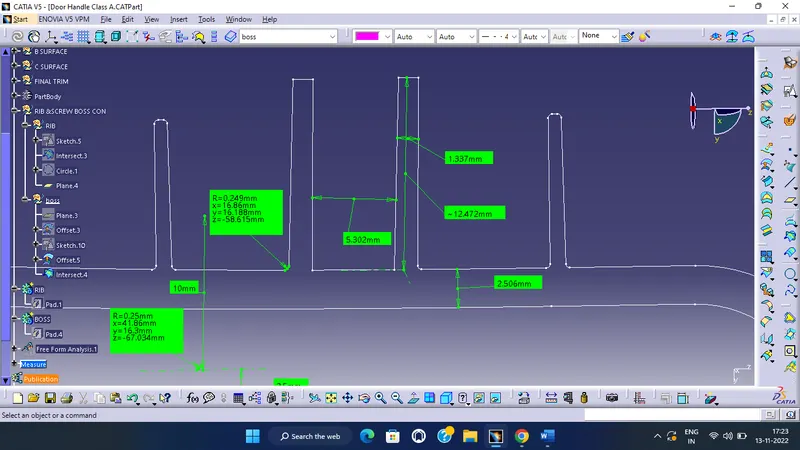
final rib and scew boss part
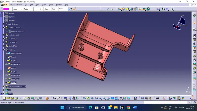
- Screenshots of the completed design in various orientations (Isometric, Front, Side, and Top View)
Isometric view
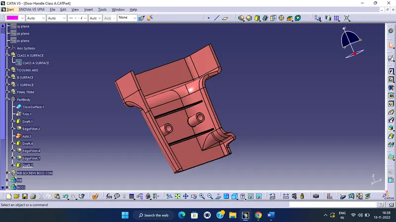
front view
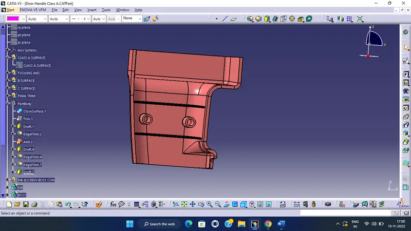
Top view
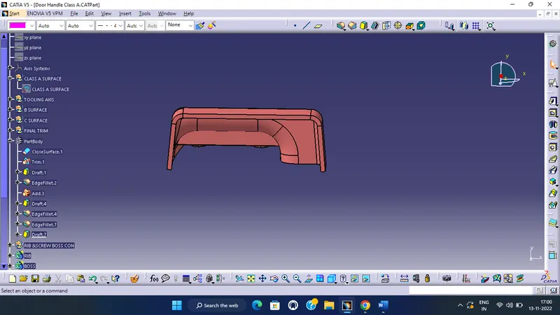
Side view
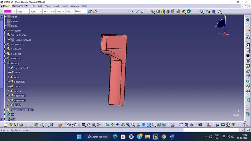
Conclusion :
Hence the Rib for the drill handle considering the design rules for rib creation and Screw boss creation and Draft analysis is also performed for the final component is successfully done.