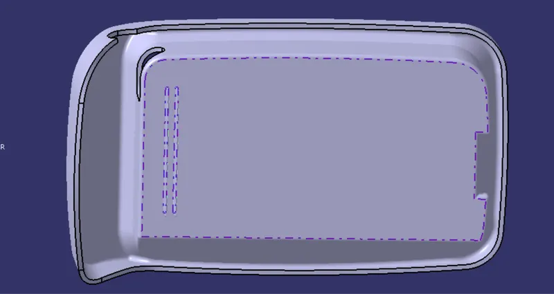
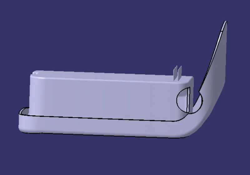
Week 9 - Attachment Feature Creation (Ribs & Screw Boss) - Challenge 1
RIBS:
Ribs are thin protrusions that extend perpendicular from a wall or plane to provide added stiffness and strength.
Designers commonly try to increase the strength of a part by making its walls thicker. Unfortunately, walls that are too thick are subject to warpage, sinking, and other defects.
PROCEDURE
STEP-1
sketch for the length of riB
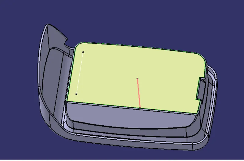
STEP-2
Extrude the sketch for 5*thickness of the component which is (5*2.5=12.5mm)
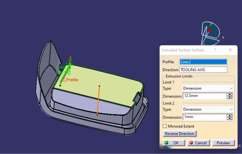
STEP-3
Thickness of the Rib should be 0.4*thickness of component (0.4*2.5=1)
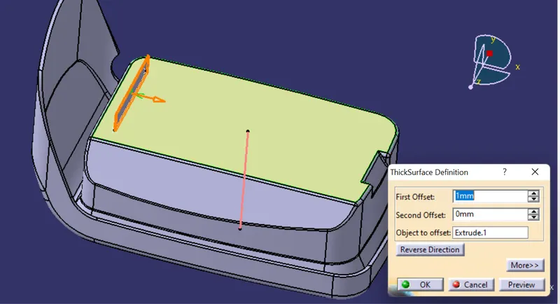
STEP-4
Giving draft to the ribs from four sides of 0.5 deg from base
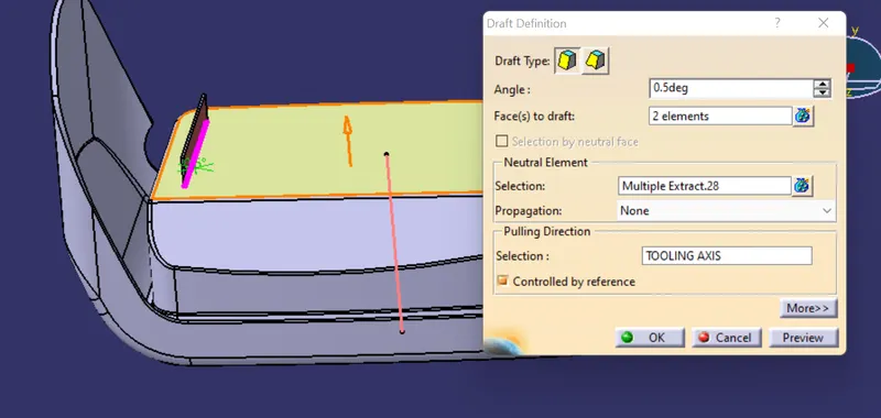
STEP-5
Assemble the Rib part body inside the main part body and give edge fillet to all faces of rib of 0.25mm
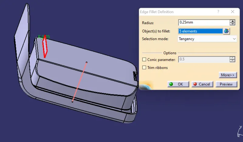
STEP-6
Creating more Ribs
height/width(mm)=3:1
width=12.5/3=4.1 (width should be >3)
here we can take 5mm for the width
Repeat STEP-1 to STEP-5 to create more Ribs
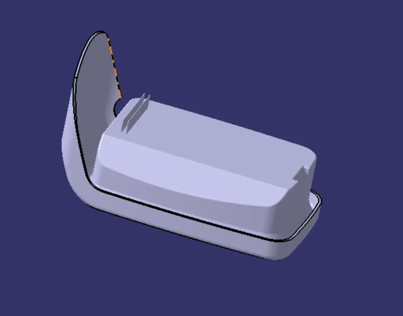
STEP-7
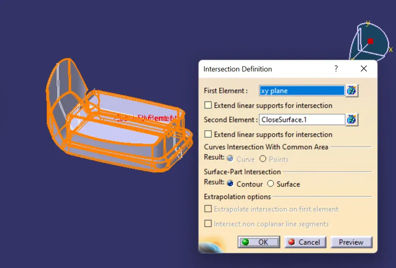
Creating intersection between the reference plane in XY direction and component part body
STEP-8
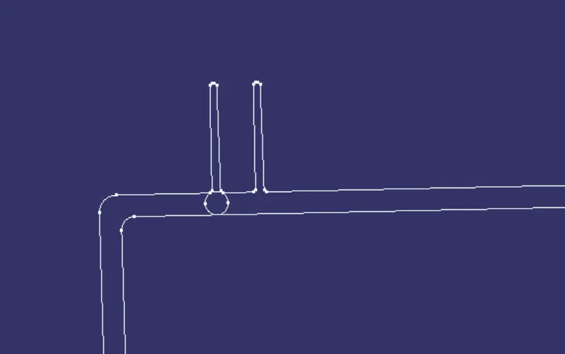
Checking for proper dimensions according to the design rules
DRAFT ANALYSIS
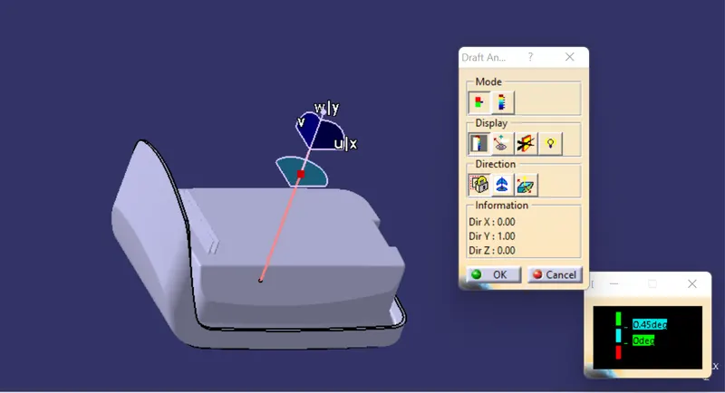
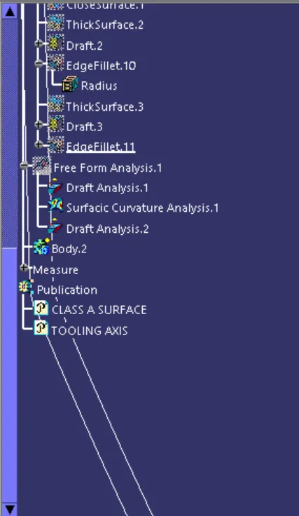
Go to INSERT-ANALYSIS-FEATURE DRAFT ANALYSIS and move the compass towards the tooling axis and chnage the range to 0.45deg
FEATURES TREE IMAGE
PART BODY