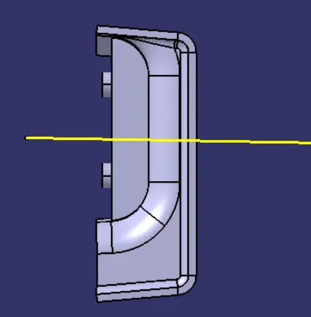
Week 9 - Attachment Feature Creation (Ribs & Screw Boss) - Challenge 1
Report -
Ribs -
Ribs are a feature in plastic injection molded parts. They are thin extensions that run perpendicular from a wall or plane. They are commonly used to provide additional support and strength to a part. An advantage of using ribs is that they increase the strength of the part without increasing wall thickness. Walls that are too thick can sink, warp or result in other defects. Their integration into a part results in less material usage; therefore a more cost effective solution
Thickness and location are essential to rib design.
General Guidelines for Ribs:
- Draft - 0.5 degrees per side minimum
- Rib thickness - 40% of base wall thickness
- Minimum thickness of rib tip = 0.75 mm
- Optional rib fillet radius - 0.25 mm maximum
- Rib height < 5 times nominal thickness of part or base wall
Thin walled parts (<1.5 mm) can often tolerate ribs that are thicker than the percentages in these guidelines. On parts with thickness less than 1.0 mm or less, the rib thickness should be equal to the wall thickness. Rib thickness directly affects the mould ability. Very thin ribs can be difficult to fill. Because of flow hesitation, thin ribs near the gate can sometimes be more difficult than those further away.
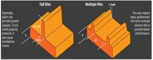
Replace large, problematic ribs with multiple shorter ones to provide better performance. Taller ribs can also provide greater support however if they are not sized properly, they can cause moldability issues.
Screw bosses -
Boss features are commonly found in injection molding designs. They are used to aid in the assembly of molded parts by providing a channel for a screw. The find use in many part designs as points for attachment and assembly. Positioning of bosses should be done away from the sidewall, and if needed ribs should be used to support them.
Normally base wall should extend to the base wall level, even if the full depth is not needed for the assembly. Shallower holes can leave thick sections, resulting in sink or voids. Deeper holes reduce the base wall thickness, leading to filling problems, knit lines or surface blemishes. The goal is to maintain a uniform wall thickness in the attachment wall.
General Guidelines for Bosses:
- Draft - 0.5 degrees on the walls of boss, both inside and outside
- Thickness - Typically 40%* of the nominal wall at the base. (more than that can cause shrinkages and hence sink)
- Height to Diameter Ratio - 3:1
- Radii - 0.25mm maximum radii.
Draft analysis of given plastic component -
Draft analysis is important here to check the feasibility of manufacturing the component. A safe draft angle of 3 degrees is provided so that the surface of the component upon shrinking does not stick to the core surface. Upon cooling within few seconds, it is the tendency of the plastic moulded component to shrink towards the core surface. This can cause diffculty to remove the final component or can even damage the surface of the component and core.
Creation of tooling axis -
There are generally four methods of creating tooling axis to check whether the component will clear the draft analysis test.
1. Along axis direction (X,Y,Z)
2. Normal to face part
3. Trial and error compass
4. Bisecting line method
Here, Trial and error compass is used to plot the main tooling axis. First the direction where major percentage of component is visible is the direction in which tooling axis is created through centroid of the component. Then the compass is adjusted by changing its angle to get the most suitable angle where the whole or majority of component is clearing the draft angle requirement. Compass is locked and the line is drawn through centroid in the compass direction. This is the main tooling axis.
Here are the images of draft analysis done of Class A surface and the final solid component -
Class A surface -
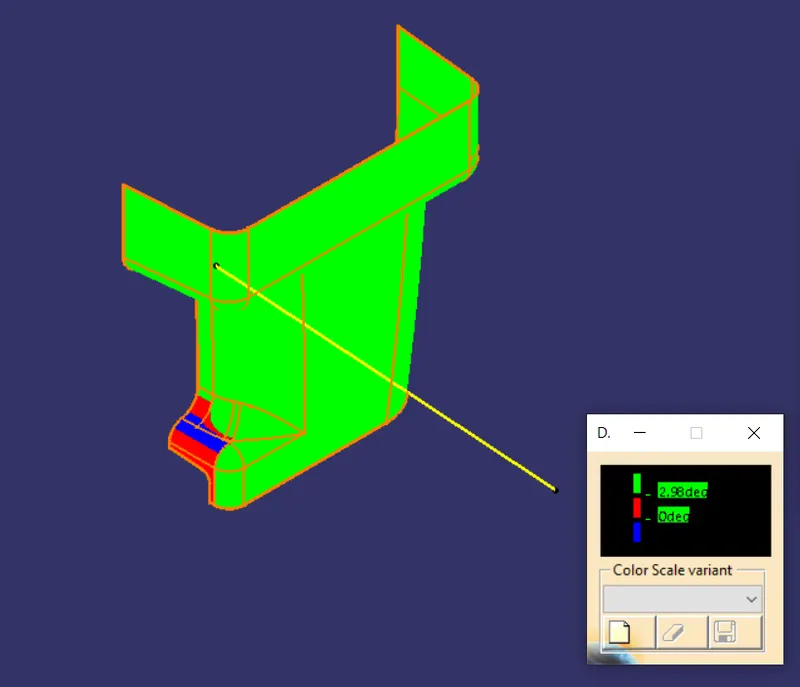
All of the component is clearing the necessarydraft angle requirement i.e. 2.9 or 3 degrees. A small portion of class A surface is blue and red in colour. This means that particular portion is not clearing the 3 degreedraft angle requirement. This can be resolved by optimising the direction of tooling axis. In this case, even the modifications in the tooling axis creation were not able to do away with that portion from not clearing. This means it is a result of draft angle less than 3 degrees in that portion of class A surface. This can be resolved by rectifying the class A surface for the minimum draft angle condition. Altogether, if a portion of class A isn't clearing then that surface must be rectified with the help of those who created it. Another methd would be to adjust the core and cavity arrangement accordingly because Class A surface cannot be always rectified at modern stages of manufacturing.
Part body -
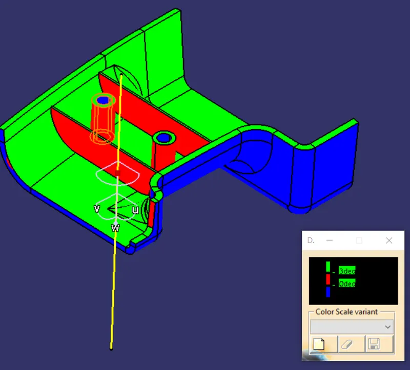
Complete part body or final component is made by joing Class A surface with Class B and C surfaces. As can be seen the inner side or B side of the component is clearing the minimum draft angl requirement of 3 degrees. Class C surfaces which are perpendicular to the tooling axis are clearing as they will due to them being being perpedicular to tooling axis. Some portions of the C surface are not clearing the draft angle condition of 3 degrees.
Attachment features such as Ribs and screw bosses in this component are clearing the minimum draft angle requirement of 0.5 degrees.
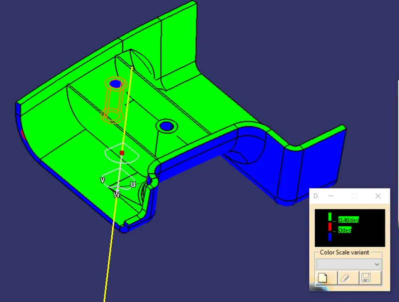
Isometric view -
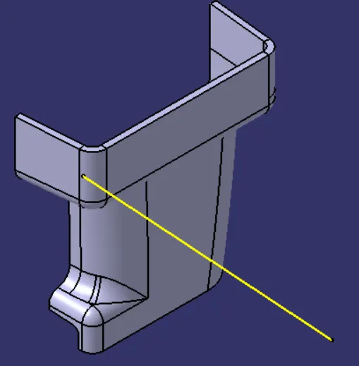
Font view -
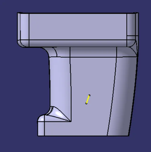
Top view -