Week 9 - Attachment Feature Creation (Ribs & Screw Boss) - Challenge 1
Door Handle
Objective
To Create the Rib and Screw boss for the Drill Handle by considering the design rules as mentioned . And to do the Draft analysis for Door Handle .
Tooling axis
The axis in which the mold or core and cavity is opens or the axis which the designer can modify or create a model by taking axis as a reference is called Tooling Axis.
Procedure to creat tooling axis.
- Checking the Class A Surface, for to check which is the perfect place to create a tooling axis.
Insert an axis system to the Class A Surface and by useing multipal extract, extract the base surface of the Class A Surface. - By selecting base as a reference surface create a point.
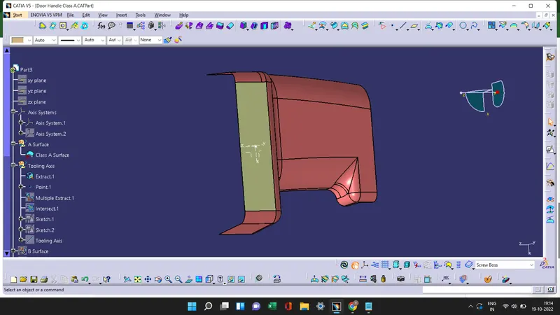
- Useing multiple extract to extract the class A Surface and take the intersection to the surface. Draw lines on the two ribs, which is intersected.
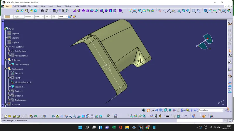
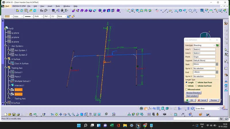
- By Bisecting line 1 and line 2 from sketch 1 and sketch 2 with the point 1 we get the Tooling Axis and publish that tooling axis
Draft analysis
Draft analysis is a method to check the draft angle of the model in various faces and to creates draft on the surface to reduce the friction in the Ejection process.
Procedure to Draft analysis
Draft analysis 1
- In draft analysis 1 we taking Class A Surface to draft.
- Check the view mode and change it to material mode.
- Select the draft analysis tool in the tool bar and select Campass in the Direction option of the draft analysis tool. Then move the campass on the tooling axis at draft direction and lock the draft direction.
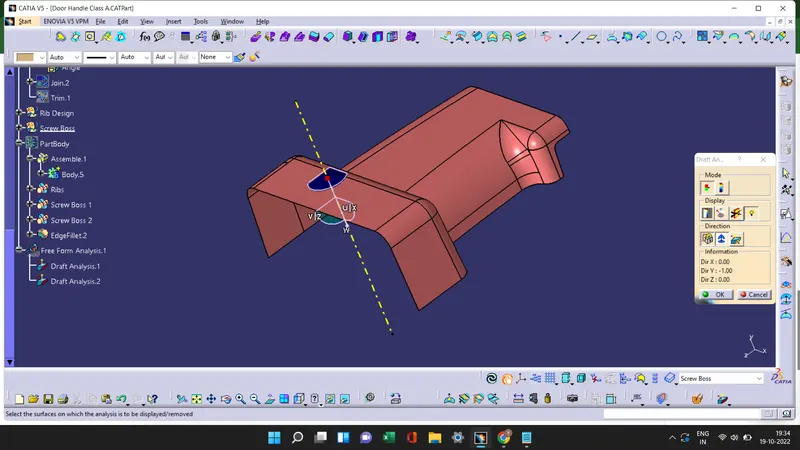
- Useing the running pointer we see the draft angle at different surfaces of the Door Handle.
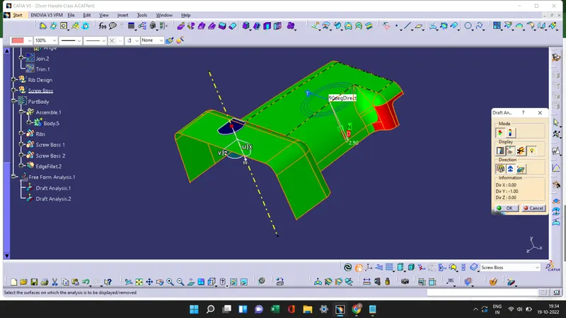
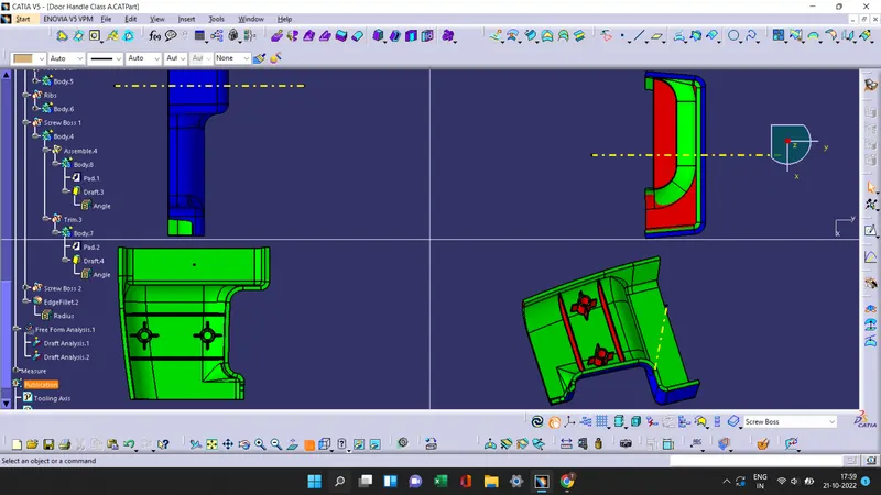
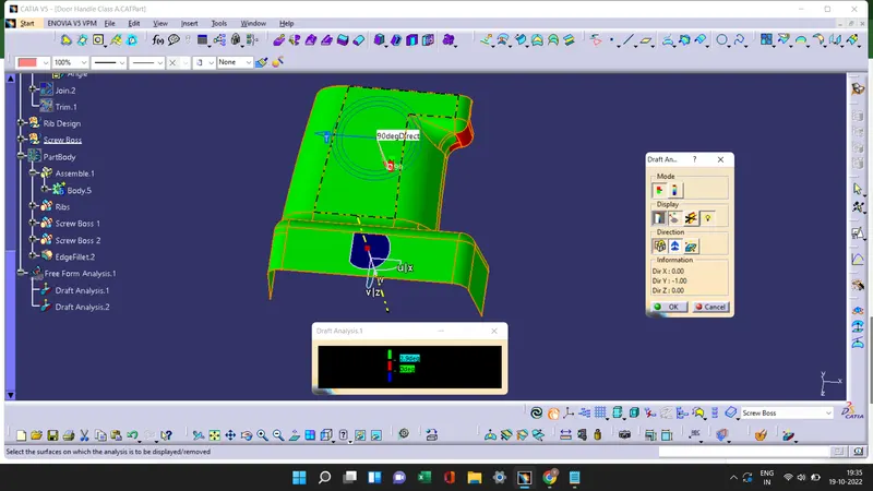
- Then by useing the color scale option we can change the Draft angle.The green color shows if the draft angle is 2.9 degree, red shows if the draft angle is between 0 to 2.9 and blue shows the negative draft angle.
Construction of Ribs and Screw Boss
Ribs
Ribs are the thin walls which are extended perpendicular surface or plane and they are used to provbide additional support to the parts.
Rib Design
- The base surface of the solid body where the rib can be created is extracted using the extract command and create a point on the that surface.
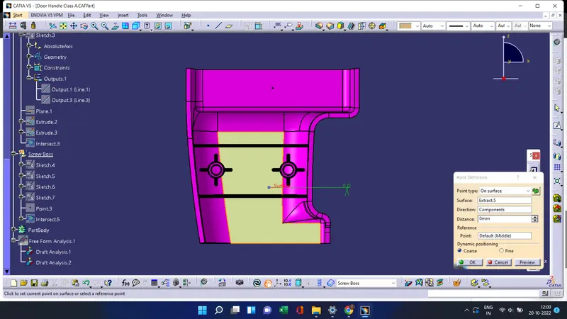
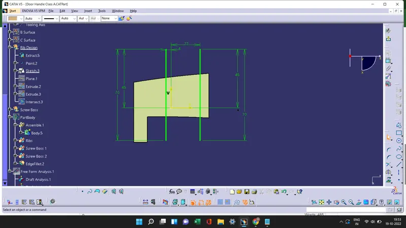
- Create a Sketch and draw the lines on the base surface and extrud them to a hight (h) and thickness(w) as per the design rules. h is calculated from the formula,
h = Wall thickness * 5
h = 2.5 * 5
h = 12.5 mm
- The thickness is calculated from the formula, w =0.4 * t
w = 0.4 * 2.5
w = 1 mm
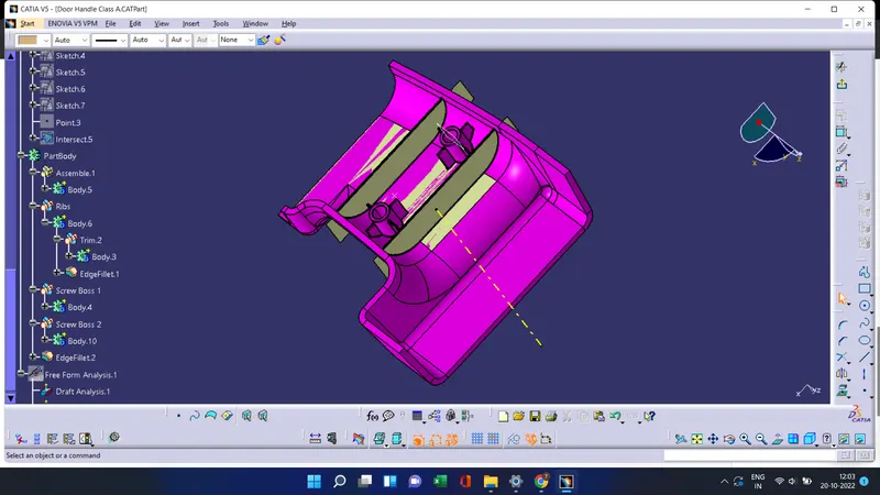
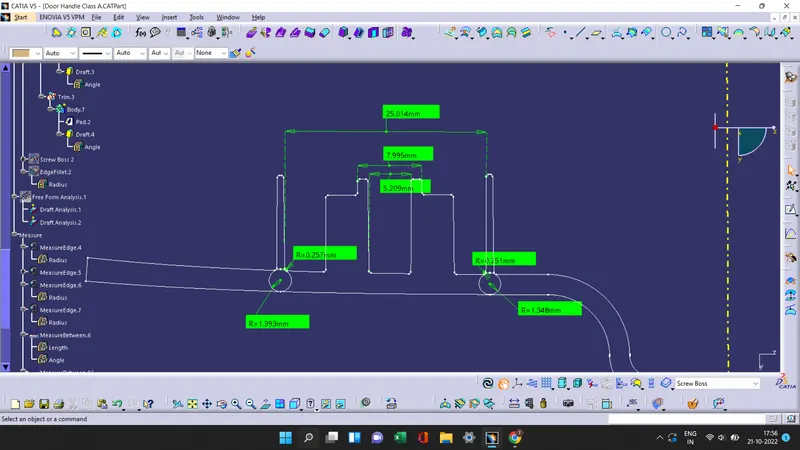
- Increase the thickness useing Thick Surface command and the draft is applied on the surface of the Ribs. The min draft according tyo the design rule should be 0.5 degree and the fillet value should be 0.25 mm.
Screw Boss
Bosses is used in many part designs as points for attachment and assembly. The most common variety consists of cylindrical projections with holes designed to receive screws, threaded inserts, or other types of fastening hardware.
Screw Boss Design
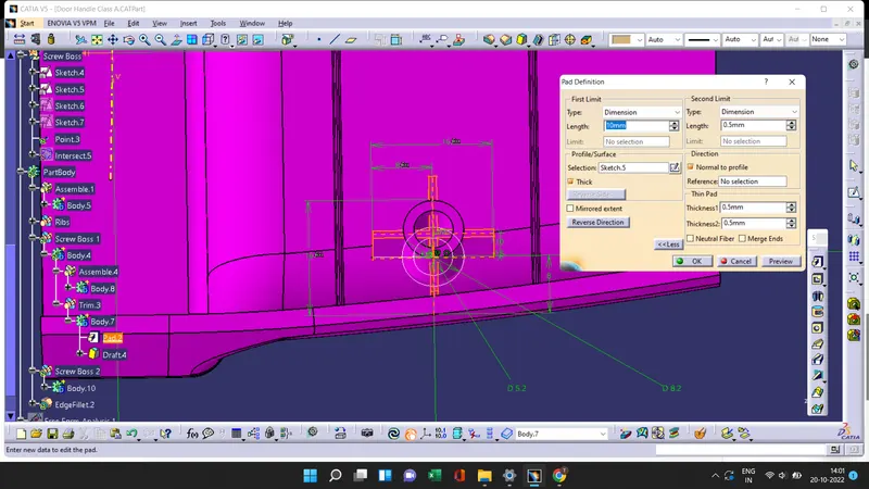
- Create two circles on the surface of the Door handle and pad to a hight h by considering the design rules, Height to Diameter Ratio - 3:1
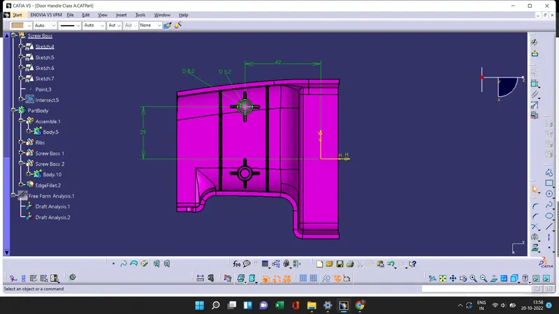
h is calculated from the formula,
h = Wall thickness * 5
h = 2.5 * 5
h = 12.5 mm
- The Thickness - Typically 40%* of the nominal wall at the base is, w =0.4 * t
w = 0.4 * 2.5
w = 1 mm
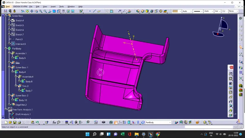
- Draft the inside and outside with 0.5 degrees on the walls of boss and give the fillet value as 0.25 mm maximum radii.
- After createing one Screw boss, it is translated to the other direction useing coordinate system and to create stiffness to the screw boss I created 4 supporting ribs to screw boss.
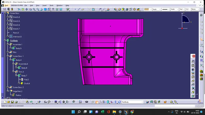
Rib root and Screw Boss thickness analysis
Draft analysis 2
- In draft analysis 2 we taking Final Solid surface to draft.
- Select the draft analysis tool in the tool bar and select Campass in the Direction option of the draft analysis tool. Then move the campass on the tooling axis at draft direction and lock the draft direction.
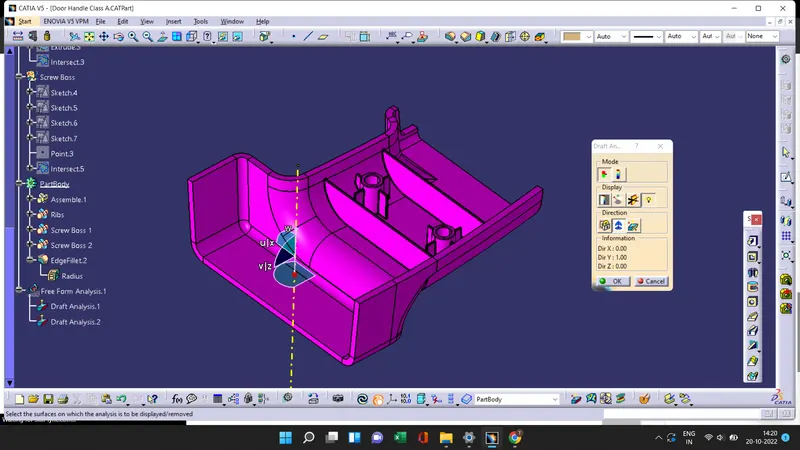
- Useing the running pointer we see the draft angle at B surface and C Surface of the Door Handle.
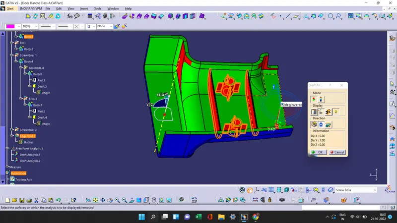
- Then by useing the color scale option we can change the Draft angle.The green color shows if the draft angle is 2.9 degree,red shows if the draft angle is between 0 to 2.9 and blue shows the negative draft angle.
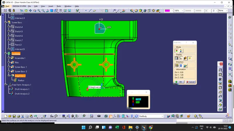
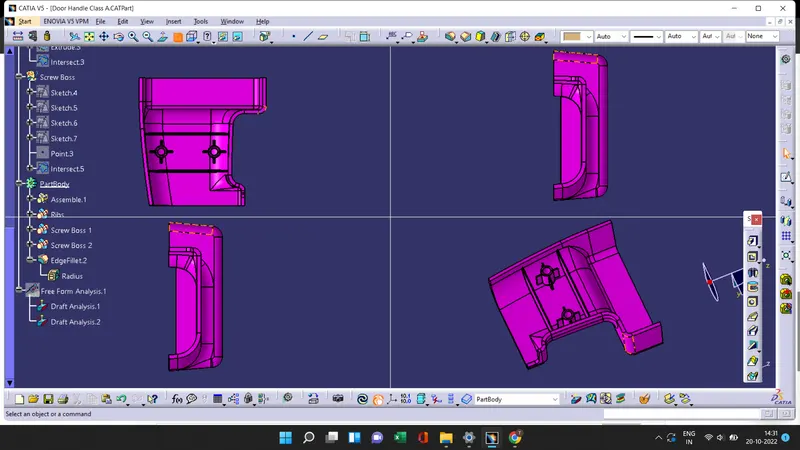
Screenshots of the completed design in various orientations