Week 9 - Attachment Feature Creation (Ribs & Screw Boss) - Challenge 1
Tolling Axis:-
It is defined as the direction in which the mold/core and cavity open. The choice of tool axis direction depends on the ease with which the parts can be ejected easily.
Analyzing the part, the easiest direction to shoot is somewhere close to the Z direction (may be inclined to it), so we made a sketch in the YZ plane of the axis system to create a bisector with respect to 2 faces that might be difficult to machine.
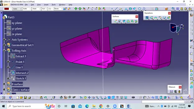
Class A Surface Draft Analysis:-
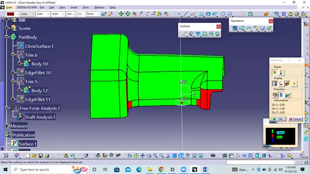
Use the compass function to set the compass to the tool direction and lock the direction using the lock function on the bevel analysis toolbar the surface is green in color, so the surface has a minimum dip angle of 3 degrees.We can check the bevel angle on individual surfaces using analyzes below the intermediate point. It shows how much slope at specific points when we move the cursor point.
Class B Surface:-
Class B surface means the thickness of the part that is not visible and is inside the part. In other words, a class B surface is a surface below a certain thickness from a class A surface. This is the surface that contains the technical aspects of the model. Class B finish is a quality finish with only minimal imperfections. Class B finish is the most common finish for outdoor surfaces. It is usually found on surfaces such as outer covers, panels and parts that are quite prominent.
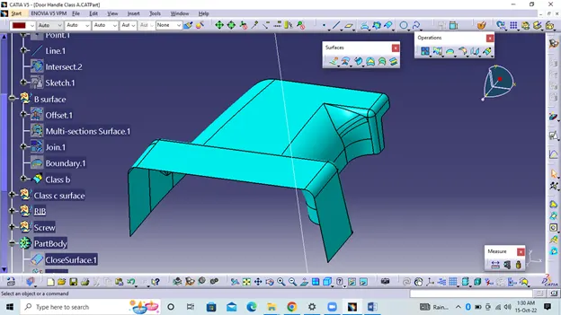
Class C Surface:-
The surface that joins Class A and Class B surfaces are Class C surfaces. Class C is often specified for interior surfaces that are not readily visible, surfaces that will be covered by another part after assembly. A Class C finish allows for more imperfections than Class A or B. Class C is often specified for interior surfaces that are not readily visible, surfaces that will be covered by another part during assembly, or surfaces that the customer feels do not need to meet a high cosmetic standard. adjustment.
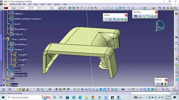
Close Surface:-
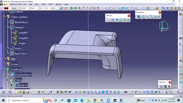
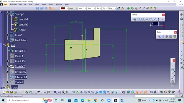
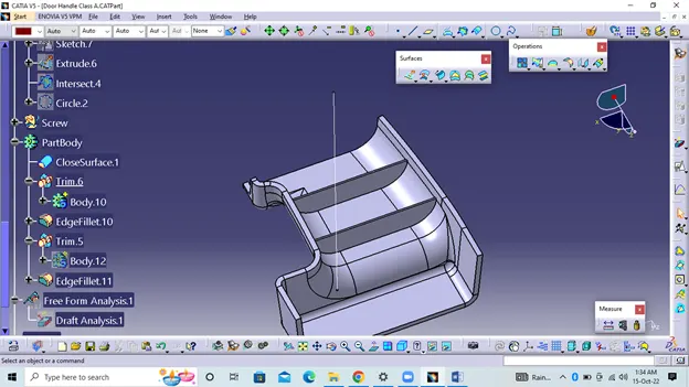
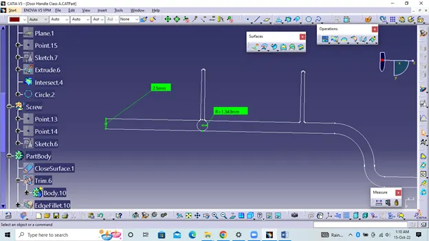
RIB Design:-
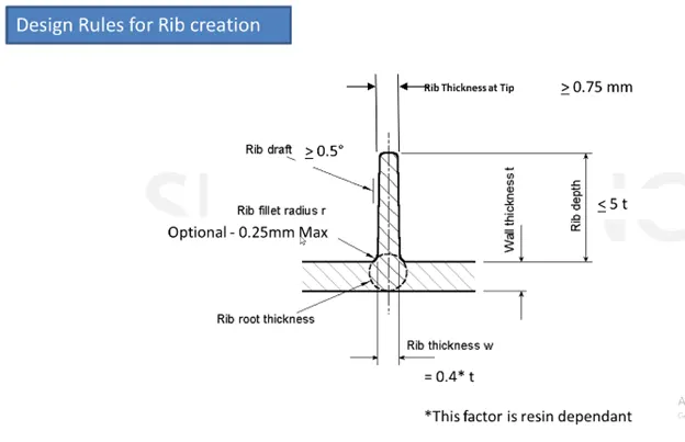
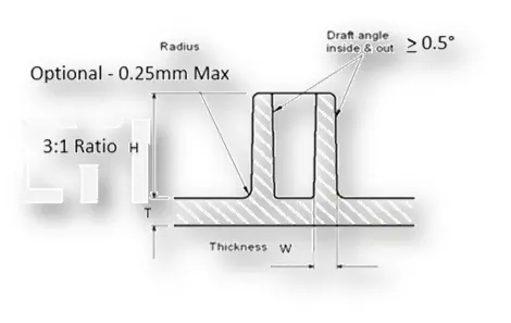
Screw Boss:-
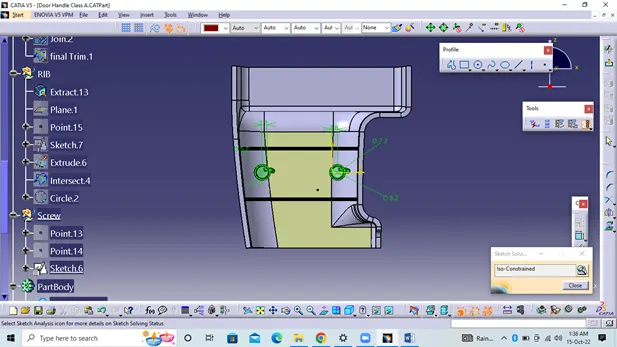
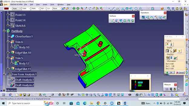
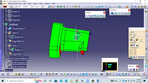
Final Component Draft Analysis :-
Design analysis is performed using the recommended design analysis tool Use the compass function to set the compass to the tool direction and lock the direction using the lock function on the bevel analysis toolbar the surface is green in color, so the surface has a minimum dip angle of 3 degrees.We can check the bevel angle on individual surfaces using analyzes below the intermediate point. It shows how much slope at specific points when we move the cursor point.