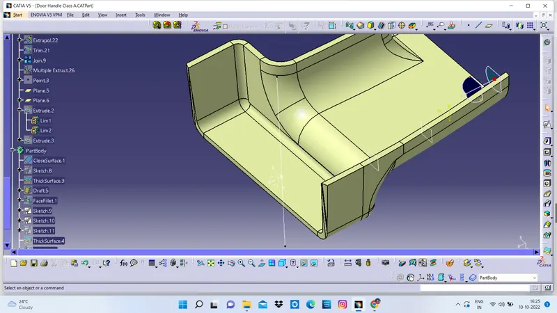
Week 9 - Attachment Feature Creation (Ribs & Screw Boss) - Challenge 1
AIM
Create the rib for the Drill Handle considering the design rules mentioned in the video.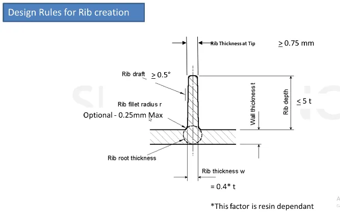
Create the Screw boss for the Drill Handle considering the design rules mentioned in the video.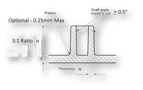
Requirements
- A detailed report should be done explaining the draft analysis and the tooling axis creation.
- An explanation should be given on the way of creating the tooling axis, particularly the Bisecting method.
- Screenshots of the completed design in various orientations (Isometric, Front, Side, and Top View)
- CATpart should be submitted as an attachment
REPORT
Screw Bosses
Boss features are commonly found in injection molding designs. They are used to aid in the assembly of molded parts by providing a channel for a screw.
Ribs
Ribs are a feature in plastic injection molded parts. They are thin extensions that run perpendicular from a wall or plane. They are commonly used to provide additional support and strength to a part.
Tooling Axis
Tooling axis is a direction in which core and cavity opens and closes. Draft angle is provided with respect to the tooling axis. While creating mold component from Class-A surface, we need to decide the tooling direction. It can be decided by visual inspection, deciding complex surfaces and bisecting method.
Tooling Axis Creation- Bisecting Method
- First check for the discontinuity of the surface received by join or boundary command. Then visual observation is done to decide which direction will be more feasible to create component.
- Few surfaces are identified which can create concern over draft angle
- A reference point is created in center of the bottom surface. And Axis system is created at that point.
- Two different cross section profiles are formed using intersection with plane.
- For first profile in xy plane, Lines are drawn on the concerned boundary intersection profile. Then line is drawn bisectiong these two lines.
Draft Analysis
To reduce the risk of damage to parts and tool while ejecting from mold a draft angle is provided to walls which are parallel to the tooling direction. It assists with releasing the part from mold.
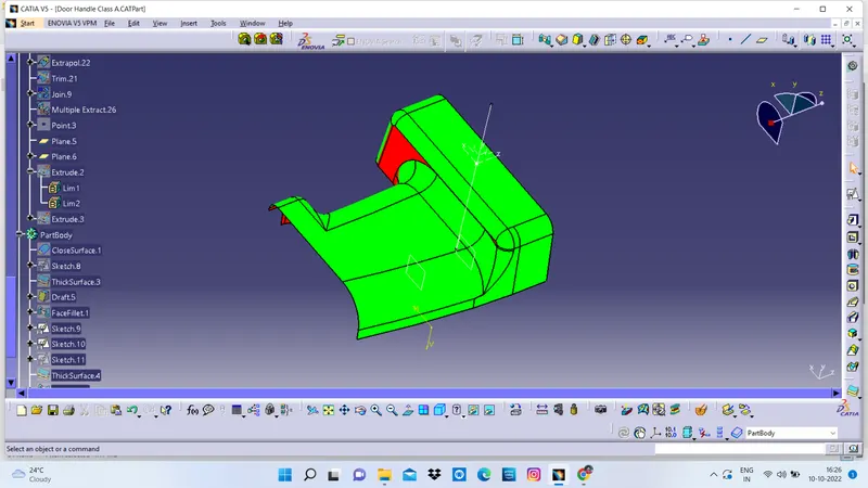
To perform Draft analysis in Catia, Draft analysis feature is used. For that First tooling Direction decided. Then make sure material view mode is used. After opening the window, align the compass with the tooling axis by dragging it on the axis. Then click on the surface or the body on which draft analysis is need to perform. In the bottom black colour window provide the minimum draft angle and then match the body color with this color scale. Green indicated draft angle is more than minimum draft angle. If it is blue then it is between 0 to minimum draft angle. And red denotes it is less than zero. By this way we can identify the areas with draft angle less than minimum draft angle and work on that area by changing tooling axis angle.