Week 9 - Attachment Feature Creation (Ribs & Screw Boss) - Challenge 1
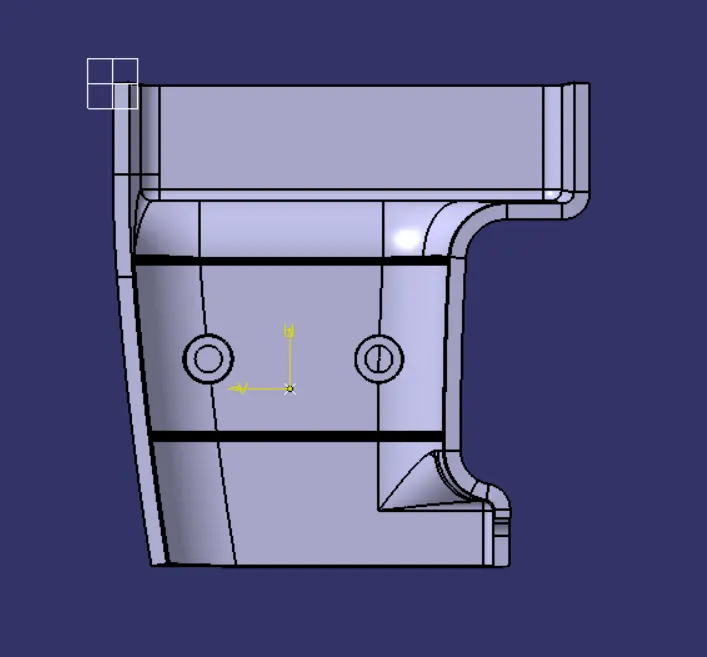
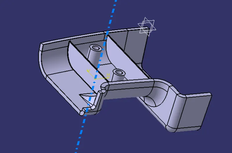
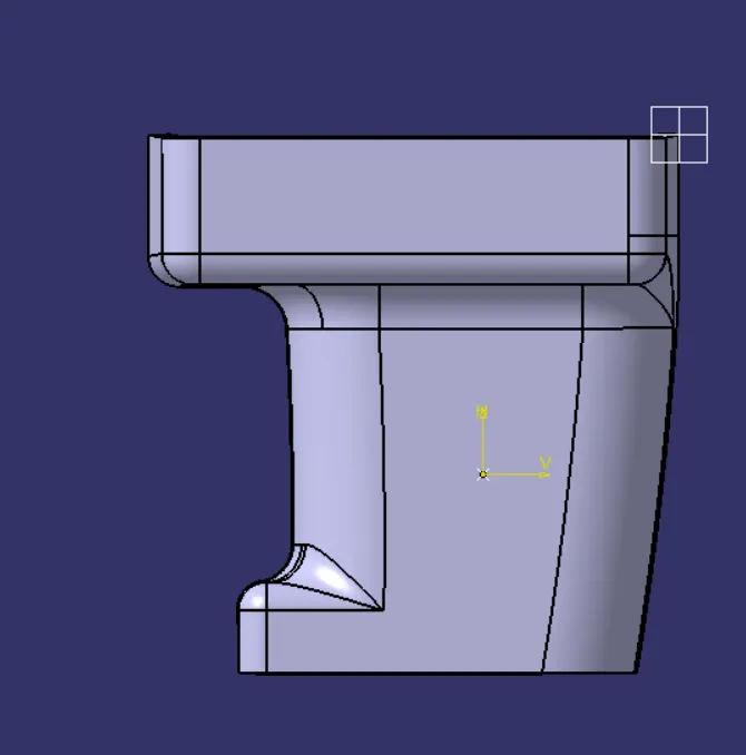
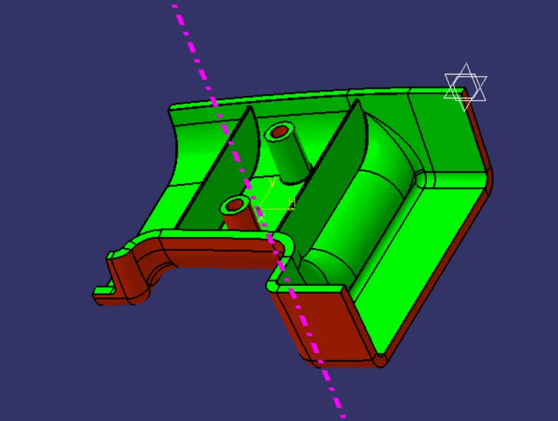
Procedure:
- Check the boundary and ensure the class A surface form a continuous boundary.
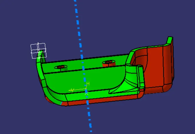
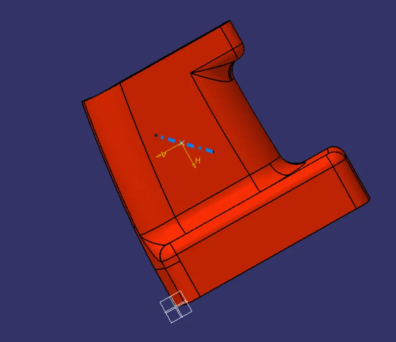
- Tooling axis is created by extracting the base surface and creating a point at centr to it. A line is drawn passing through the point in Z direction which is considered as a tooling axis.
- Draft analysis is performed to verify the tooling axis direction
- The Class A surface offset by a distance of 3mm to form a class B surface.
- Class C surface is made through the boundary and Class C and Class A are joined.
- The joined Class C and A is trimmed with Class A to form a closed part.
- Using Closed surface feature in part design a solid part is made.
- Draft analysis is performed on the solid body finally.
- Rib and Screw Boss are designed as per the design rules ad draft analysis is performed