Week 9 - Attachment Feature Creation (Ribs & Screw Boss) - Challenge 1
DOOR HANDLE
AIM
Create the rib and screw boss for the Drill Handle considering the design rules and perform Draft analysis.
TOOLING AXIS
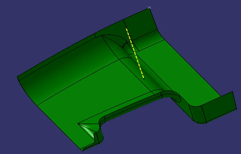
- The tooling direction is used to find the direction in which the part is ejected out of the mold or it is the direction in which the core and cavity are moved and the part is ejected.
- The draft on the part should be positive in order to manufacture the part easily. The draft angle should be positive with respect to the tooling direction.
- To create the tooling axis, we need the proper orientation or view that gives the correct features and draft available in the component.
- So here the component view from the Y-direction gives the proper view for the tool to see the features present in the geometry.To create the tooling axis from the Y direction we need the tooling axis from the other direction that gives the wall draft angle.
- The bin base center will be the initial tooling axis for the coin holder. The tooling axis created by following steps
- The base surface is extracted.
- Then the center point is created using the point > on the surface at 0
- At the point created the axis system is created.
- After that switching the view of the model to the X direction and creating the tooling axis. Using the intersect in the ZY plane to get the boundary lines. Then the lines are created along the slant surfaces.
- Here the wall lines form the zero degrees angle with the base. So the final tooling axis will be perpendicular to the base or in the Y direction from the center point.
DRAFT ANALYSIS
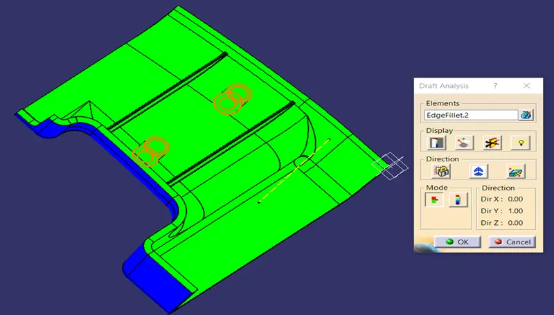
- To perform the draft analysis the view parameters are first set to material mode.
- Then go to Insert >>analysis>>feature draft analysis.
- First, select the axis system and drag the axis system to align and coincide with the tooling axis and lock the orientation. This axis system defines the draft direction according to the tooling axis.
- Switch on the color scale and set the minimum draft value. Here it is set to 3 degrees and it will be displayed in green color.
- Any draft angle below 0 degrees will be shown in red color. Now select the running point tool to measure the draft angle at the various locations and then if all surface passes the draft analysis switch on the light effect that will show the component in green color if the component has the required draft angle.
- The final draft analysis shows the green color surface having the draft angle above 3 degrees and red or cyan color shows the draft angle below 0 degrees.
- All the surfaces with green can be easily manufactured with the injection molding but the read color surface which is a negative draft cannot be ejected or manufactured with the main tooling axis.
- The solution for this is to have another tooling axis that captures all the rest surfaces but this is not feasible or the last option to make changes in the A-class surface.
CREATING THE RIB
- Ribs are thin wall protrusions that extend perpendicularly from a wall or plane. They are usually found in clusters offering support to a plane that would have otherwise been too thick, but can also be stand-alone support for a single wall.
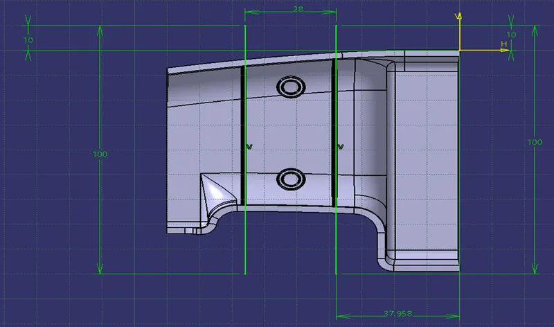
- They are commonly used to provide additional support and strength to a part. Thickness and location are essential to rib design.First, the base surface where the rib has to be created is extracted using the Extract command.
- A positioned sketch is created and the profile for the rib is drawn.
- Next, the profile is extruded, to find the height,h=Wall thickness * 5
=2.5*5
= 12.5 mm
Therefore, the height is 12.5 mm
- The extruded surface is thickened The extruded surface is thickened, Thickness,w=0.4*t
=0.4 2.5
=1mm
Therefore, the thickness of the rib is 1 mm
- The draft is applied to the sides of the ribs. As per the design rule, the ideal draft angle is 0. Deg.
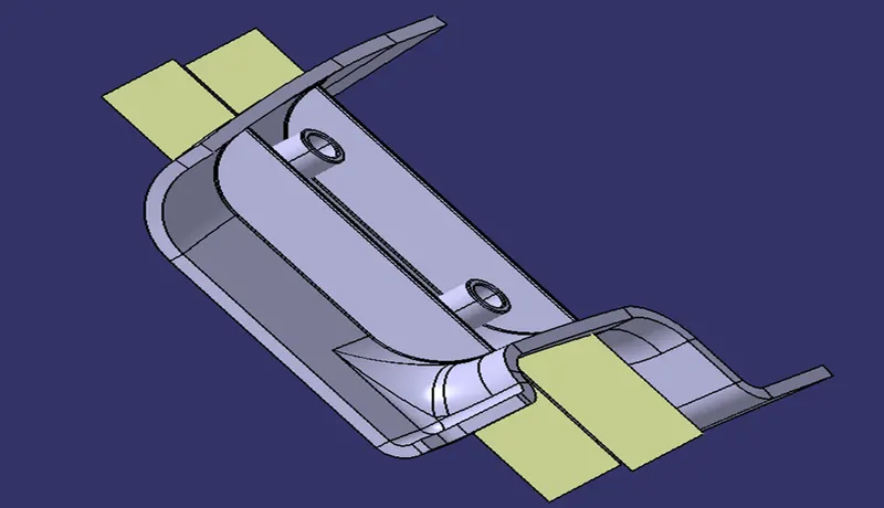
- Then fillet is applied to the faces of the rib. As per the design rule, the fillet can be 0.25 mm.
RIB ROOT THICKNESS
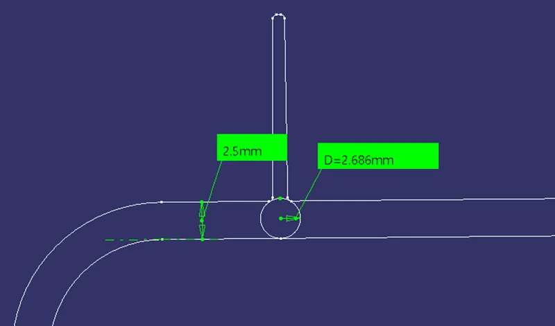
To check for the Rib root thickness, We have to take an Intersection with the XY plane and the Coin holder component. Once we get to the intersection we have to create a tri[1]tangent circle at the rib area and measure it. The value must be within 30% greater of the wall thickness.
CREATING THE SCREW BOSS
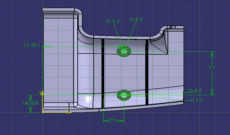
Screw Boss features are commonly found in injection molding designs. They are used to ai in the assembly of molded parts by providing a channel for a screw. Their primary use is to strengthen holes or slots in the surface present in the part model.
Design rules consider while creating a screw boss
- Thickness
- Draft
- optional radii
- Boss gussets
- Type of ejection
The construction process of creating the screw boss is explained below:
For thickness, the design rule is as follows,
Thickness,w=0.6*T
=0.6*2.5
=1.5 mm
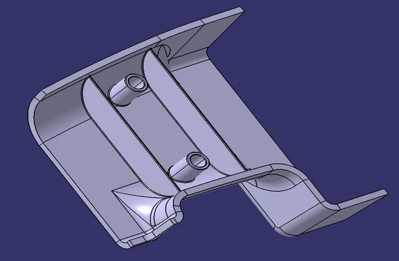
Therefore, the thickness of the boss can be 1.5 mm per side. In this case, we have considered the size of the screw boss as M06.
- Once the sketch is completed, then it is padded using the Pad'command. The height to diameter ratio can be 3:1.
- Next, the draft is given to the boss. As per the design rule, the draft given for screw boss is 0.5 deg.
- Then fillet is applied to the faces of the rib. As per the design rule, the fillet can be 0.25 mm.
RESULTS
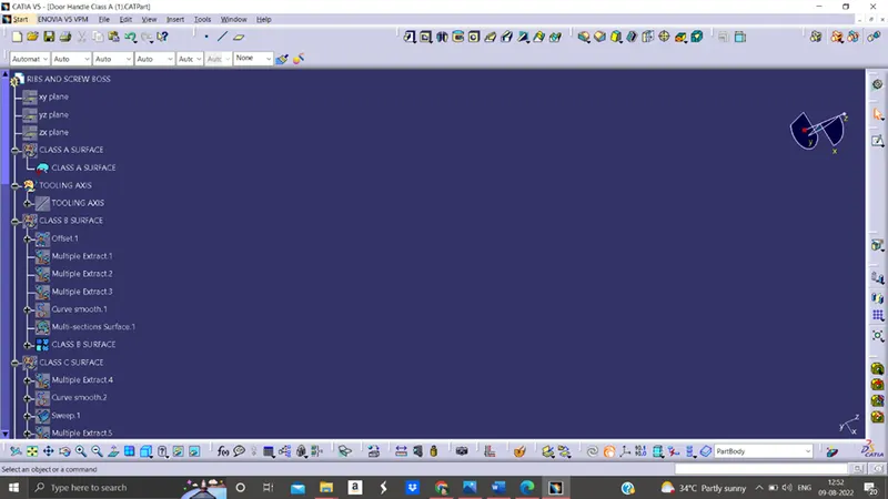
FEATURE TREE 1
FEATURE TREE 2
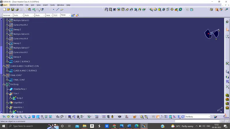
FEATURE TREE 3
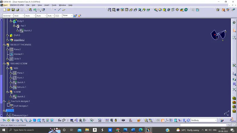
FEATURE TREE 4
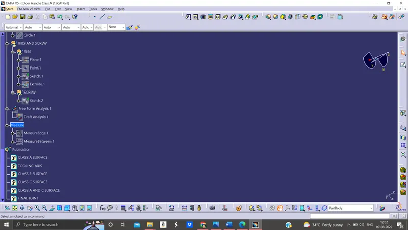
FRONT VIEW
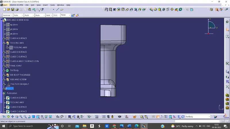
TOP VIEW
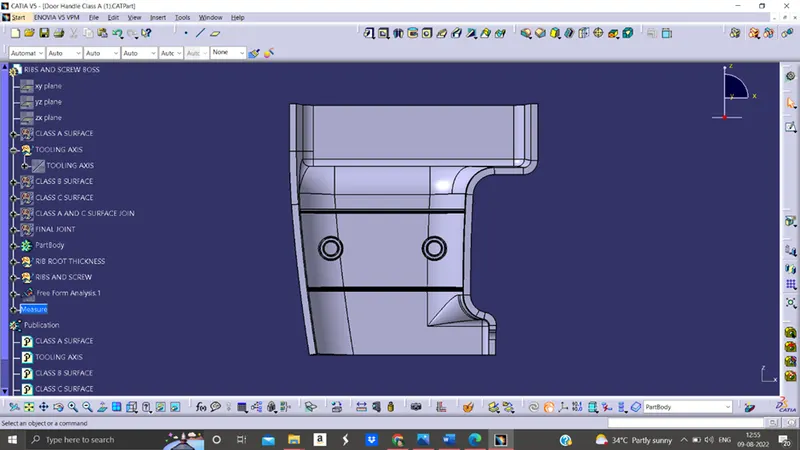
BOTTOM VIEW
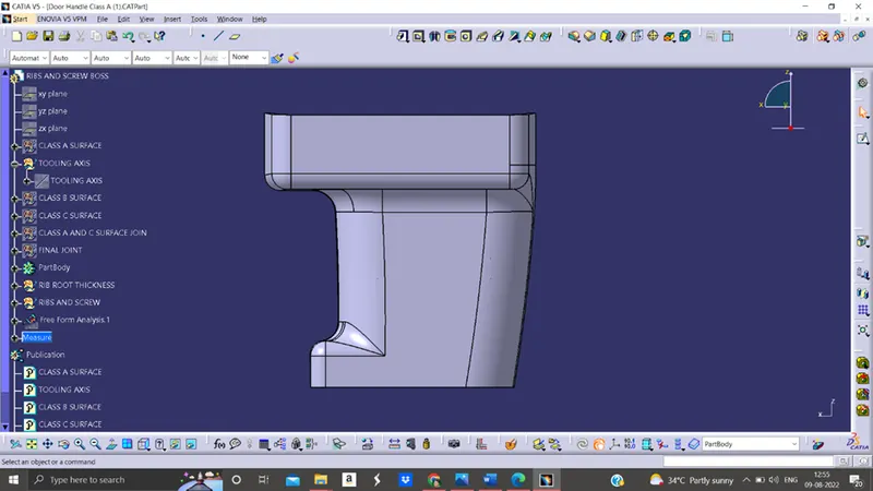
ISOMETRIC VIEW
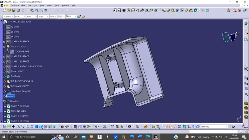
CLASS A SURAFCE
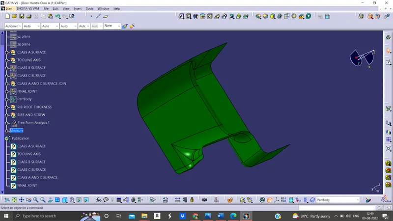
CLASS B SURFACE
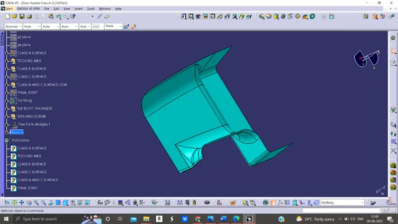
CLASS C SURFACE
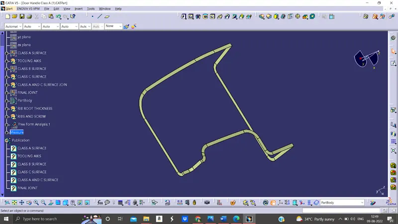
CLASS A AND C SURFACE JOINT
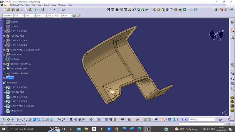
FINAL JOINT SURFACE
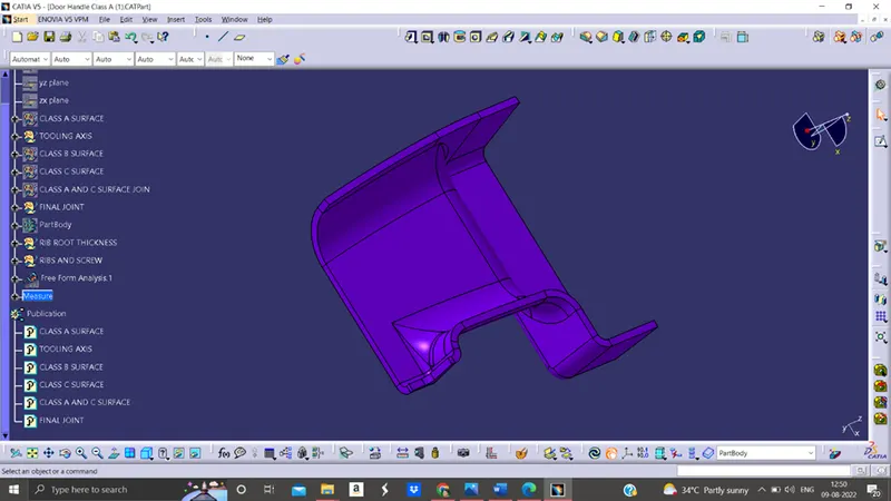
CONCLUSION
- Created Tooling axis
- Created Class B and Class C surface from provided Class A surface.
- Created solid part out of surface modelling.
- Created engineering features.
- Draft analysis of Class A surface and final part is also done.