Week 9 - Attachment Feature Creation - Challenge 2
Attachment Feature Creation of Door trim for Dog House
Introduction:
- The main goal of this project is to create a dog house of plastic material for door trim components that comply with OEM standards utilizing the provided of door trim components.
- The Correct Tree Structure should be followed using a boolean operation.
- The name of a geometric set should be based on proper Standards.
Aim:
- This design aims to create a dog house on Plastic components using the given surface following the OEM standard.
- Perform the draft analysis and join the dog house on the door trim.
Class A Design:
- The automobile design sector employs creates the class-A surface.
- It describes the aesthetic Surface final it requires final production surface data.
Class B Design:
- The class-B surface is the second surface from the class-A surface reference that has a specific thickness.
- This surface includes Plastic design engineering components.
- These must also be "error-free" and smooth but are not bound to the same requirements as class A surfaces.
Class C Design:
- Compared to Class A or B, the Class C finish allows greater flaws.
- Class C specifications are frequently used for interior surfaces that are difficult to see, surfaces that will be hidden by another part when it is completed, or surfaces.
Design Methodology:
- Add the Door Trim class A surface design to the CATIA program.
-
Choosing the tooling axis of the Door Trim design.
-
Then Creating a class B surface.
-
The surface of class C creation.
-
Joining the change Verify that the class A, class B, and class c surfaces and add the dog house are all closed surfaces.
-
Create a solid body from the surface by using the Close Surface function.
-
Finally, Perform the Draft analysis of both the door trim and dog house and finalize the plastic component.
Class A Surface:
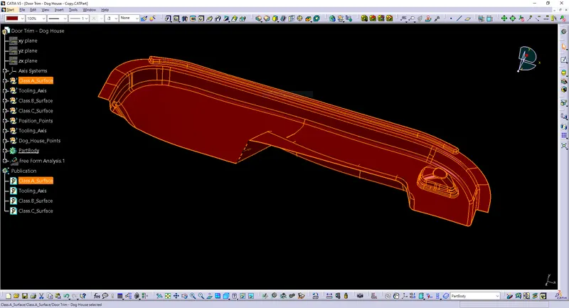
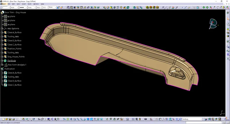
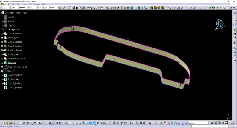
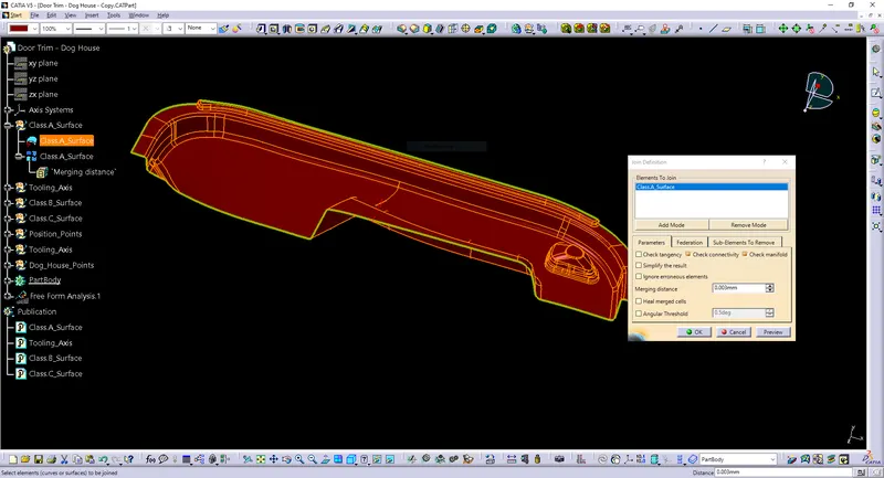
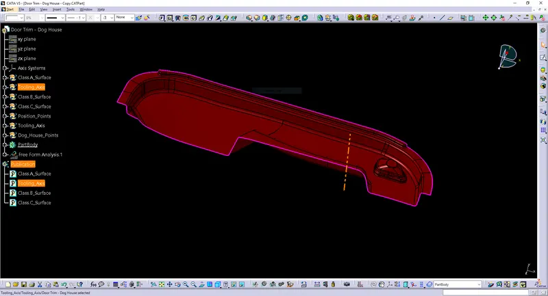
- In Class A surface, must be closed.
- If it is not closed or any invalid features are noticed the part will not going to generate.
- The part is fully constrained, use the join method and give distance propagation and join it all.
Creating of Tooling Axis:
- Select Insert > Axis System from the menu bar or click Axis System . ...
- Select the point as shown to position the origin of the axis system you wish to create. ...
- If you are not satisfied with the x-axis, for instance, click the X-Axis field and select a line to define a new direction for the x-axis.
Class.A & Class.C_Joining:
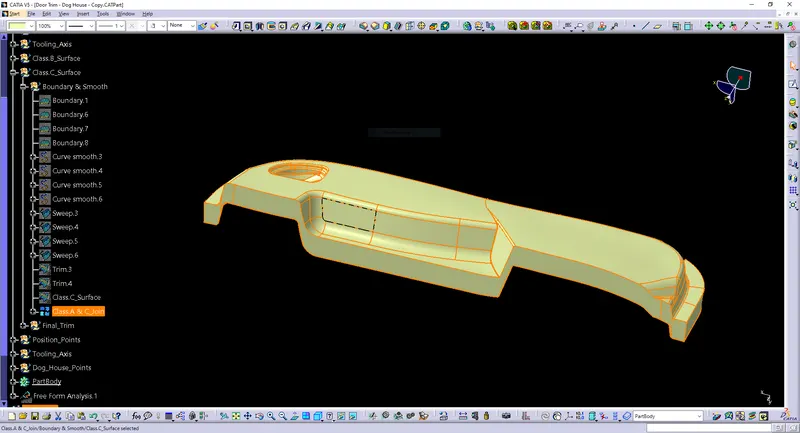
- In a process of joining A & C, it should be a closed surface.
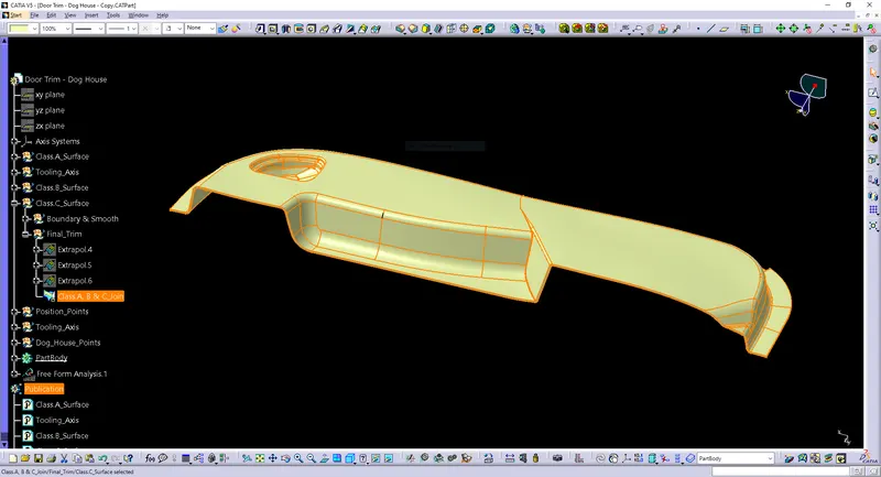
Class.A & Class.B & Class C_Joining:
Draft Analysis:
- The draught analysis approach is used to determine whether our CAD-created part model is capable of being manufactured given the draught condition employed.
- Here, the component should be simple to remove from the panel dies (for sheet metal parts) or Mold (in the case of plastic).
Draft Analysis on Class-A Surface:
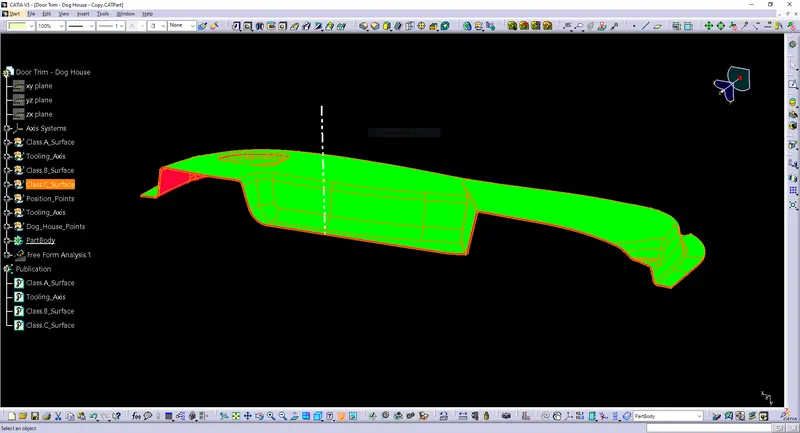
- Enter analysis, feature draught analysis, and insert.
- Align the compass and the tooling axis.
- Click the surface to verify that it is within the draught values' permitted range.
- The surface should be green, and the nominal input value for the column should be 3 degrees.
- As a result, the draught analysis on the class-A surface was completed satisfactorily.
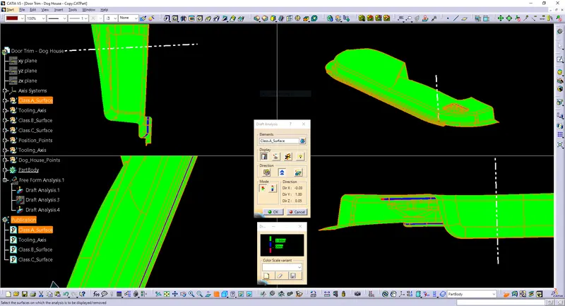
Draft Analysis on Final Part:
- Using the draught analysis command, you can determine whether the part you drafted will be simple to remove.
- In this kind of analysis, zones on the investigated element are identified by color ranges where the deviation from the draught direction at any given place corresponds to predetermined values.
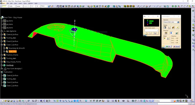
Orientation of Class A, B, & C, Surfaces:
Front View:
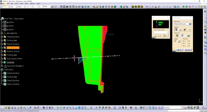
Top View:
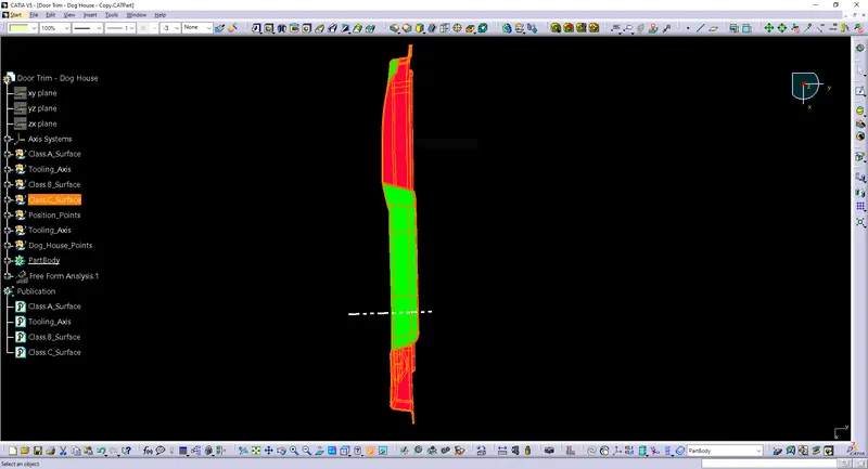
Left View:
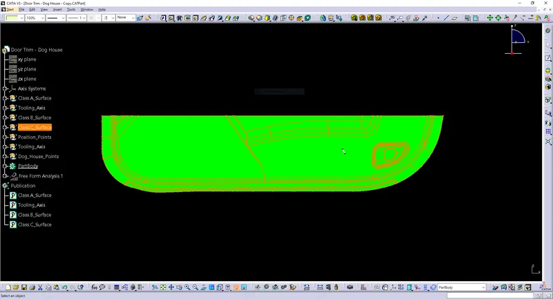
Isometric View:
Dog House:
- Plastic design makes use of an engineering feature called a dog house.
- Dog houses serve as a support element to increase their strength, other engineering features like snaps, locators, and screw bosses may be mounted on them.
Draft analysis is performed on dog houses to prevent component breakage during ejection from the mold cavity. - On the B-surface, the dog house and other engineering components are constructed.
Creation Of Dog House:
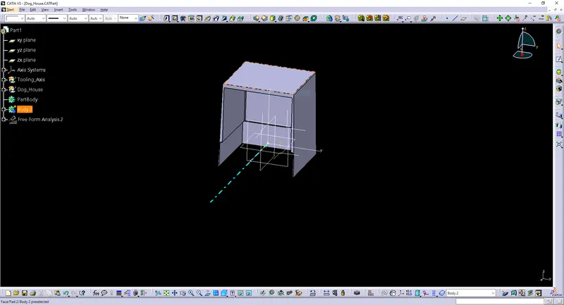
- Dog houses are made to prevent screw bosses from leaving a sink mark on the CLASS-A surface and to solve length problems when connecting screw bosses to other parts.
- It also comes in handy when the part needs screw bosses that are perpendicular to the tooling direction.
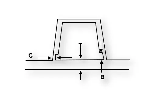
- The dog house should be at least 12 millimeters wide, and its thickness should be 2.5 millimeters thicker than the main wall.
- The dog house must be between 30 and 60 millimeters high.
- The base draft for the canine house inside is 0.5 degrees to kick the bucket drawing.
- The inside of the dog house has a maximum draft of 1.5 degrees to the die drawing.
Procedure for the Dog House;
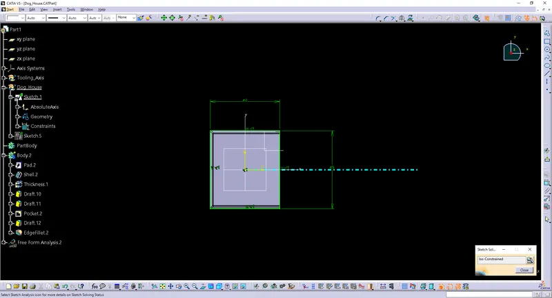
- The creation of a side core axis is the first step.
- For creating the side core tooling axis, I have selected the normal to-the-point method.
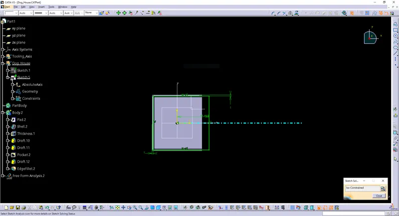
Draft Analysis of the Dog House:
- The Draft Analysis command allows you to determine whether the draft's component can be easily removed.
- Color ranges are used in this kind of analysis to pinpoint areas on the analyzed element where any deviation from the draft direction corresponds to particular values.
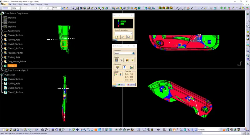
- The steps for conducting the draft analysis are as follows: switch the component's view mode to customized parameter mode, then select materials for the shading mode.
- Then, from the insert menu, open the featured draft analysis tool.
- Then drag and align the compass on the Tooling axis after clicking on the Use the Compass to define the current drafting direction.
- After that, click on the component to complete the draft analysis and lock the draft direction.
Representation of the color range:
- Green color - Verify whether the draft meets your needs.
- Blue color - Determine the error.
- Red color - Make a distinction between the cavity and the core.
Draft the Dog House and analysis with the Side Core and their Axis:
Outside Draft for the Dog House:
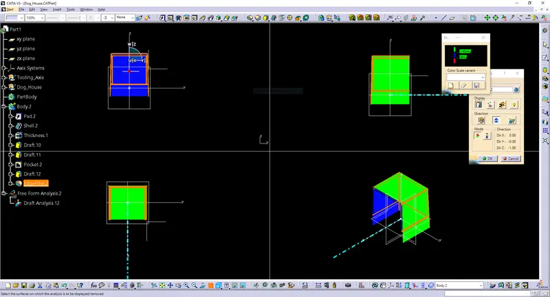
- The ideal position for the outside draft is 1.45 degrees.
- The Z-axis ought to be the direction.
Inside Draft for the Dog House:
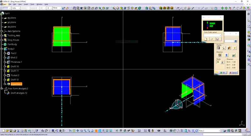
- The ideal position for the inside draft is 0.45 degrees.
- The X-axis ought to be the direction.
Draft analysis of the final dog house and door trim:
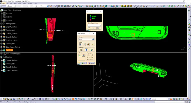
Conclusion:
- Using the door trim's CLASS A surface, the created main tooling axis, and the side core tooling axis, the CLASS B and C surfaces were successfully created.
- The examination of the dog house and the last part in its drafted and fixed on the entryway trim and concluded.