Week 9 - Attachment Feature Creation - Challenge 2
AIM
TO Create the Dog House for the Door Trim considering the design rules
TO Create the Dog House for the Door Trim considering the design rules mentioned in the video. Consider the thickness of the part to be 2.5mm
METARIAL SELECTION:
- ABS
WHY THIS MATERIAL IS USED:
- ABS has a low melting point which enable its easy use in the injection moulding process and 3D printing .It also has high tensile strength and is very resistance to physical impacts and chemical corrosion,which allow the finished plastic to withstand heavy use and adverse environmental condition.
- High dimensional stability (mechanically strong and stable over time).
- High surface brightness and excellent surface aspect.
DOG HOUSE
Dog house is an engineering feature used in plastic design. Dog houses are used as support feature. Sometimes other engineering features like snaps, locators, screw bosses are mounted on them to increase their strength.
Dog houses are subjected to draft analysis to prevent breakage of the component during ejection from the mould cavity. Dog house and oher engineering components are built on the B-surface.
OBJECTIVE
- Create Tooling axis for the given CLASS -A surface.
- Create the CLASS B and C surfaces of door trim using the given CLASS-A surface.
- Create final surface model and convert it into solid body using close surface command in the part design workbench.
- Create side core axis for the dog house
- Create Dog house on the B surface by considering the design rules.
- Perform draft analysis for both Class-A surface and Final part body.
CLASS A SURFACE :
Class-A surface means visible surface. It gives the aesthetic of the component which is created by the styling team and gives to the part design engineer to create the part with all engineering aspects.
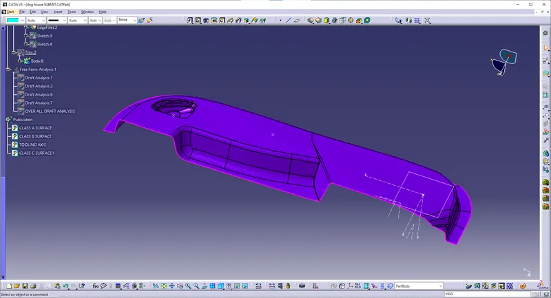
Check for continuity of the given surface using Join or Boundary commands.
If there are no gaps on the A surface, create tooling axis.
Procedure for Tooling axis creation
- Check the best possible tooling direction by manually adjusting the compass.
- By analysing it is found that y axis as tooling direction would clear most of the faces without any difficulties.
- Now extract any surface and create a mid-point on it.
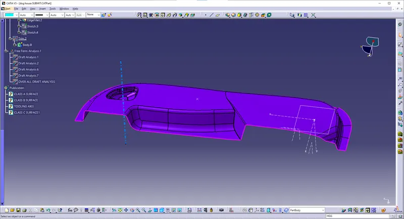
- Then create a dummy axis creating a line on the point and direction along the y axis.
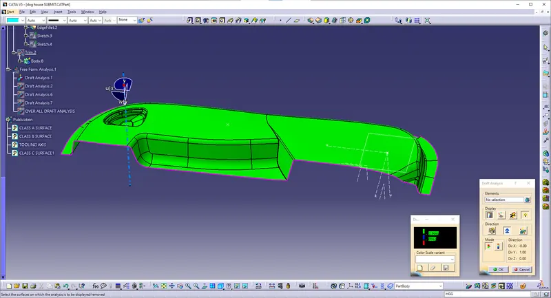
- Perform draft analysis to find whether the given axis clearing the draft analysis. If not create a new tooling axis.
DRAFT ANALYSIS FOR CLASS A SURFACE:
CLASS-B surface creation
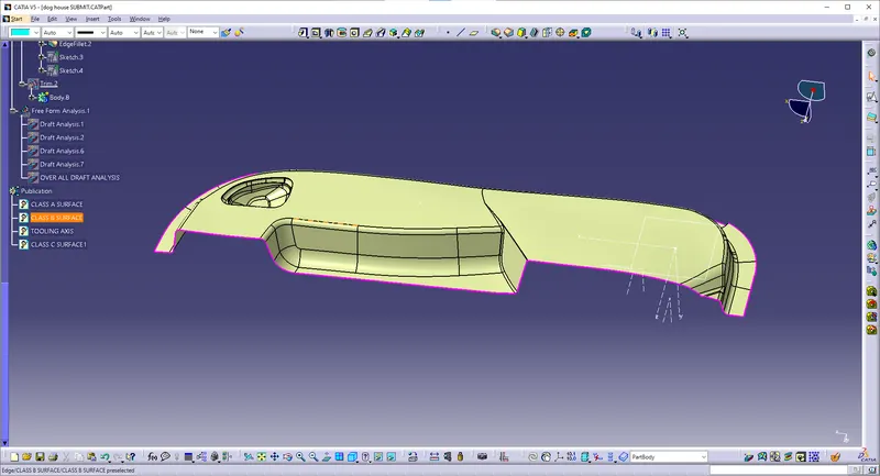
Class-B surface means thickness of a part it is not visible and is inside part. In other words, Class-B surface is a surface below a certain thickness from the class-A surface. This is the surface that contains engineering aspects of a model.
- Create offset surface of CLASS-A about 2.5mm inward direction.
- Check for the discontinuity and rework on the offset surface using extract, multi-extract, multi sections surface.
CLASS-C surface creation
Surface that joins class-A and class-B surfaces is class-C surface. Class C is often specified for interior surfaces not readily visible, surfaces that will be covered by another part when assembled
- Create the sweep surfaces with reference to surface and tooling axis by multi extracting the CLASS-A boundary
- Join the sweep surfaces by using commands like extrapolate, trim, multi section surface.
- Finally join all the sweep surfaces and ensure the continuity of the CLASS-C surface.
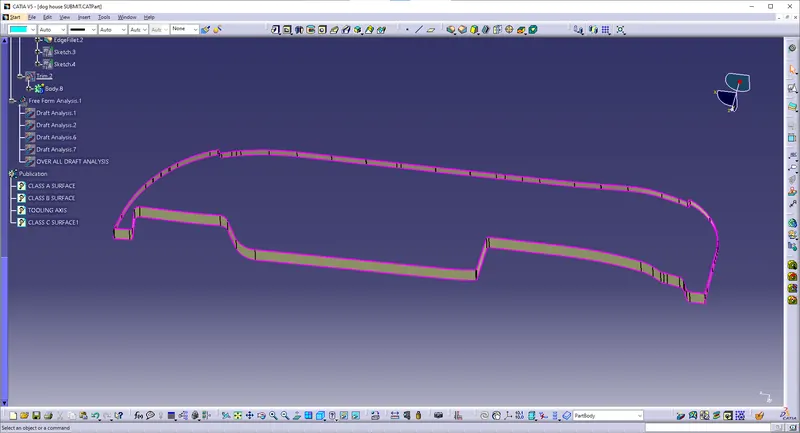
A&C JOIN:
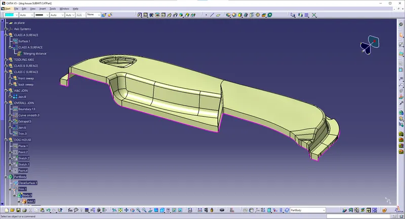
Creating the Final surface
- For creating the Finals door trim surface, join the CLASS-A and CLASS-C surface together.
- Then Extrapolate the B surface little bit outward direction to make sure that there would not be any gap when trimming with joined surface.
- Then trim the extrapolated CLASS-B surface with Join surface (CLASS-A and CLASS-C)
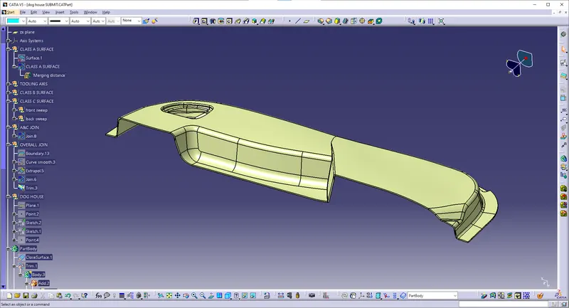
DRAFT ANALYSIS FOR OVERALL SURFACE:
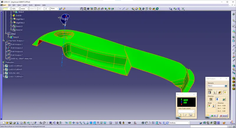
PART BODY OF CLOSED SURFACE :
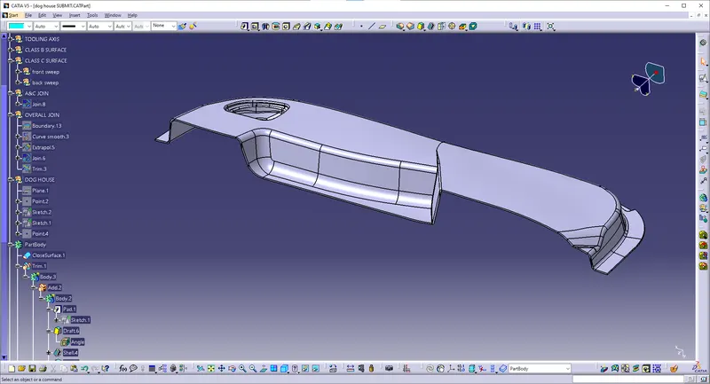
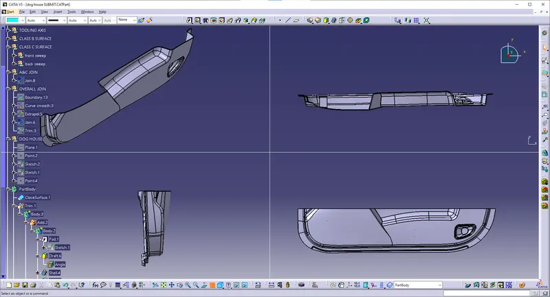
FOUR VIEW OF CLOSED BODY SURFACE:
- TOP VIEW
- FRONT VIEW
- SIDE VIEW
DOG HOUSE Creation
- Dog houses are designed to avoid SINK MARK created on the CLASS-A surface by screw bosses and to solve the length issues when giving screw bosses which need to be assembled to other components.
- It is also useful when perpendicular screw bosses are required on the part to the tooling direction.
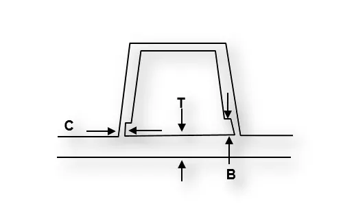
- C thickness should be 40% of the main wall thickness T
- Minimum width of the dog house is 12 mm.
- Height of B should be 3-6 mm
- Minimum draft for the do house is 1.5 degree to die draw.
- Lifter - Internal cutter (cutout)
- slider- outernal cutter (cutout)
- 60mm max height of doghouse [3.0-6.0]
- draft angles as 3degree or less than 3degree.we can use 1.5degree as a nominal degree of outer face of dof house
- inner draft angle of dog house should be 0.5degree
sink marks between 3-6mm height
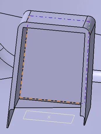
SKETCH FOR DOG HOUSE:
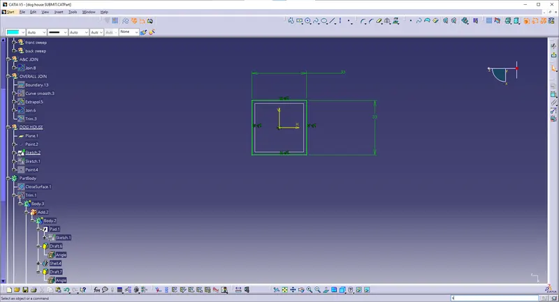
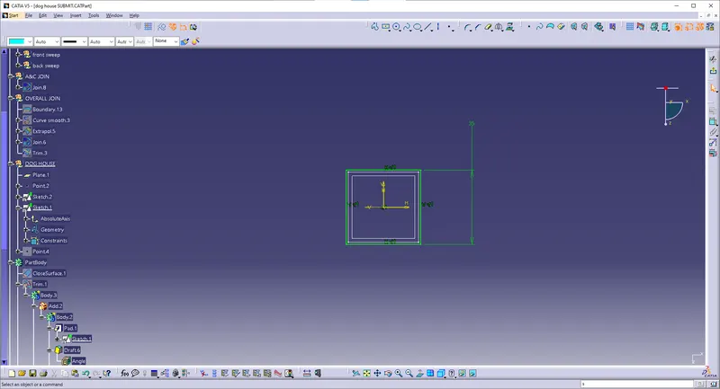
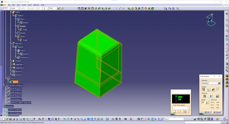
DRAFT ANALYSIS FOR OUTER DOG HOUSE
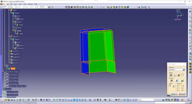
DRAFT ANALYSIS FOR INNER DOG HOUSE:
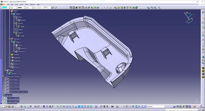
CLOSED BODY WITH DOG HOUSE:
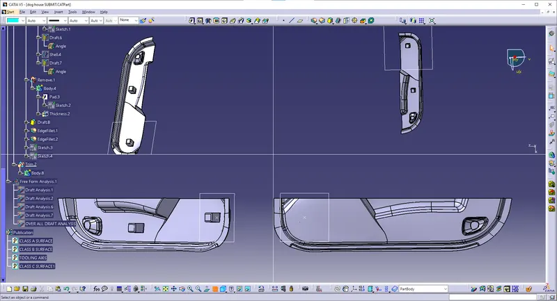
FOUR VIEW OF FINAL BODY:
FAMILY TREE :
