Week 9 - Attachment Feature Creation - Challenge 2
AIM:
- To Create the Door Trim Component from the given Class-A surface.
- To Create the Tooling axis for the given Class-A Surface meeting the requirements of the draft angle.
- To perform the Draft analysis on the model.
- To Create the B Side Feature in the component by following the design rules.
Design Methodology
Class-A surface means visible surface. It gives the aesthetic of the component which is created by the styling team and gives to the part design engineer to create the part with all engineering aspects.
Given CLASS-A surface
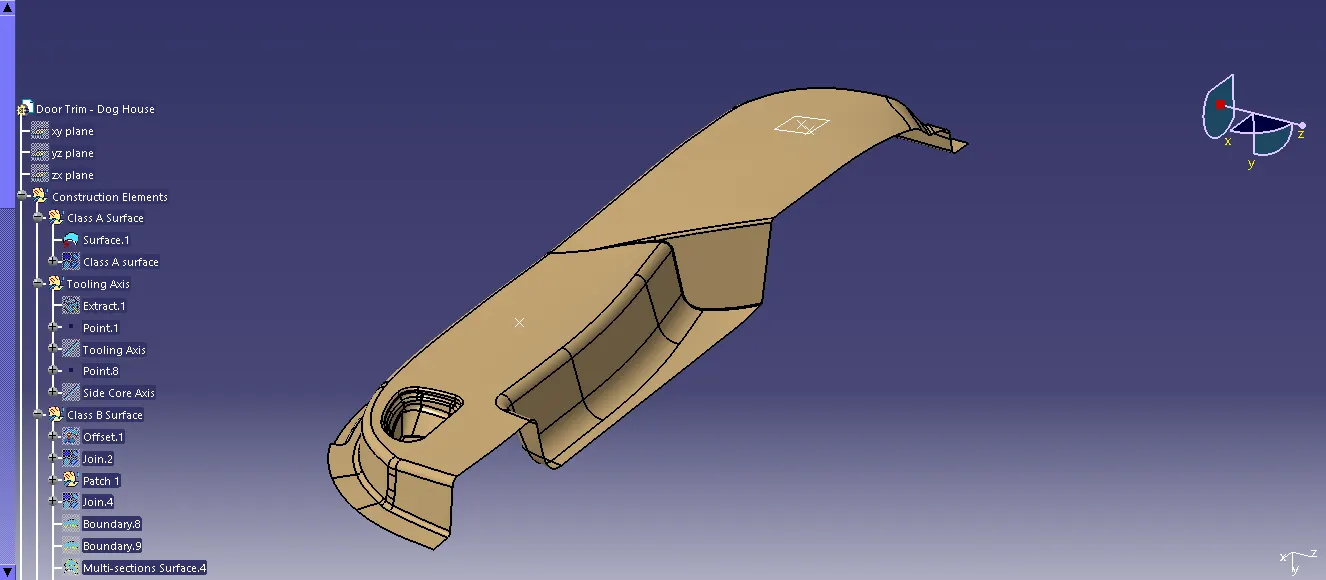
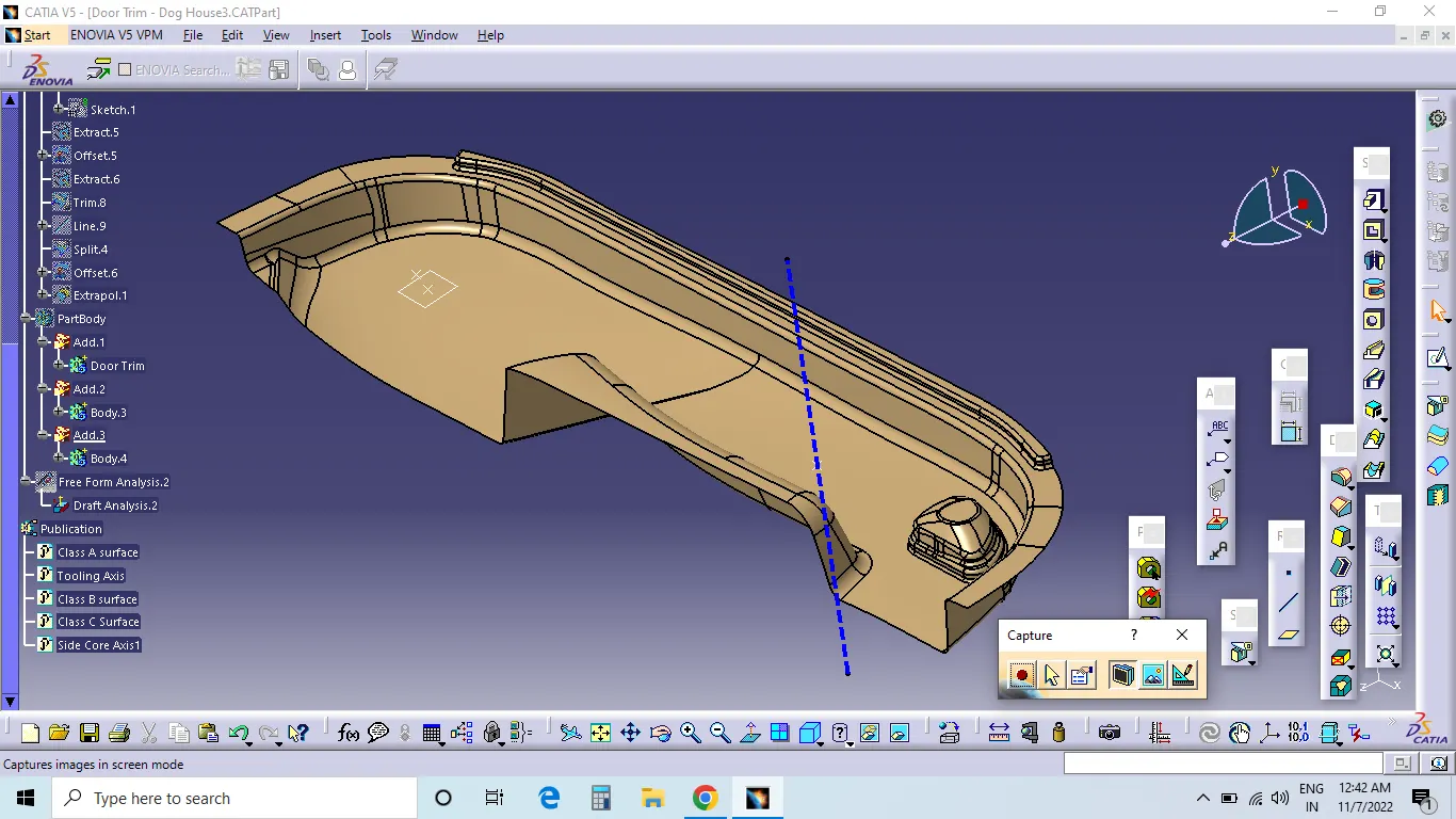
Tooling Axis :-
- Tooling axis here created is by selecting one of the natural axes as it clears the draft.
- Here, tooling axis is created by extracting one of the surfaces for creating a point and a new axis is created at that point.
- So, a flat face is extracted and created a point at its centre. Axis is also created at that point.
- Now, line is created using line tool and giving line type as point-direction and selected the point and direction for creating tooling axis and tooling axis is created along x direction.
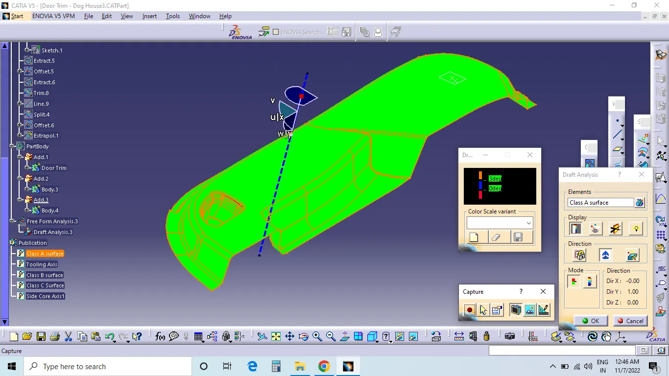
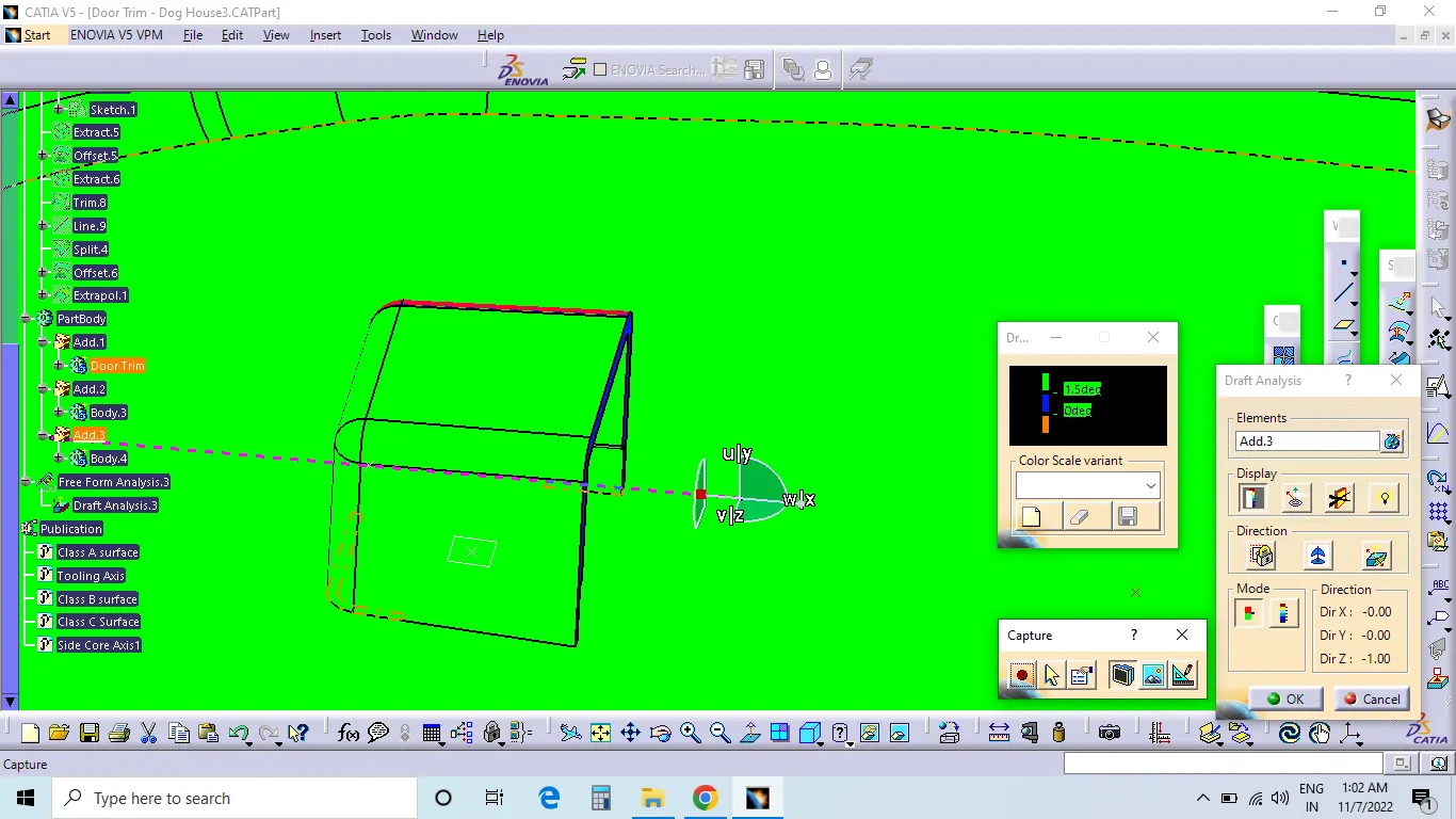
Draft Analysis for Class A Surface:-
- Change the view mode to material shading
- Align the Compass with Tooling axis.
- Lock the draft direction and perform the Draft analysis.
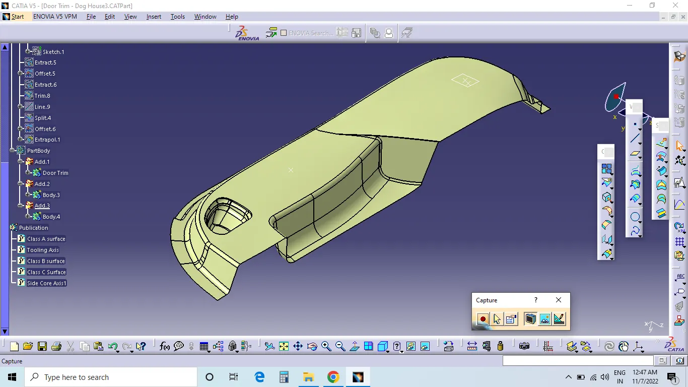
Creation of Class B :-
- To create the class B surface, offset the class A surface inside as per our thickness requirement (here the thickness is 2.5mm, so I offset the class A to 2.5mm inside).
- Once the offset is created, we can observe some patches on the offset surface by taking the boundary for the offset surface, those patches are formed due to the fillets on the class A surface.
- We covered the patches by using the different surface commands (multi sections surface, fill, blend) in the Generative Shape Design workbench.
Creation of Class C :-
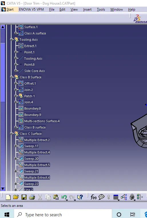
- To create the class C surface concerning the boundary of the class A surface, I used the sweep command. Initially, I extracted the boundary of the class A surface with tangent continuity, and I sweep the extracted boundary concerning the surface at 93deg (for draft angle) for 5mm to intersect properly with the class B surface.
- Once we sweep all the surface boundaries of class A, extrapolate the swept surfaces until both surfaces got intersected properly, and trim them to remove extended extrapolated surfaces to get a proper sweep boundary throughout the entire surface, including the centre hole of the bumper.
- Now, join both class A and sweep boundary to get the complete class C surface.
- Now Class A surface and Class C surface is joined.
- Now Class B surface is also trimmed with the obtained surface to get the closed surface.
- Boundary check is done to check for any open boundaries in the part. The closed surface then obtained moved to part design and close surface tool is used to obtain the part.
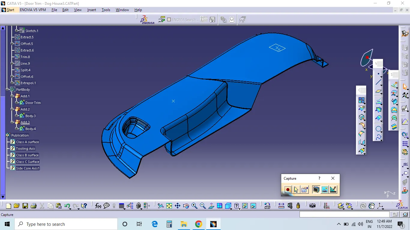
Creating the final surface of Door Trim :-
- First step is to join the CLASS-A surface with CLASS-C surface.
- Then Trim the Joined surface with CLASS-B surface to achieve the final Door surface.
- Go to the part design work bench and using the close surface command create the base bracket solid part body.
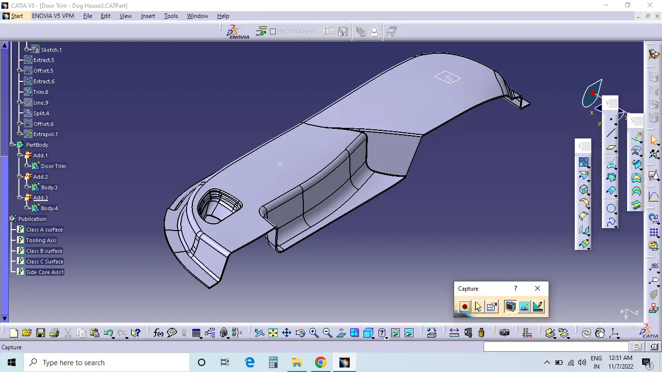
Draft analysis of the Final part body:-
Same procedure for the draft analysis of CLASS-A surface is followed.
- Change the view mode to material shading
- Align the Compass with Tooling axis.
- Lock the draft direction and perform the Draft analysis.
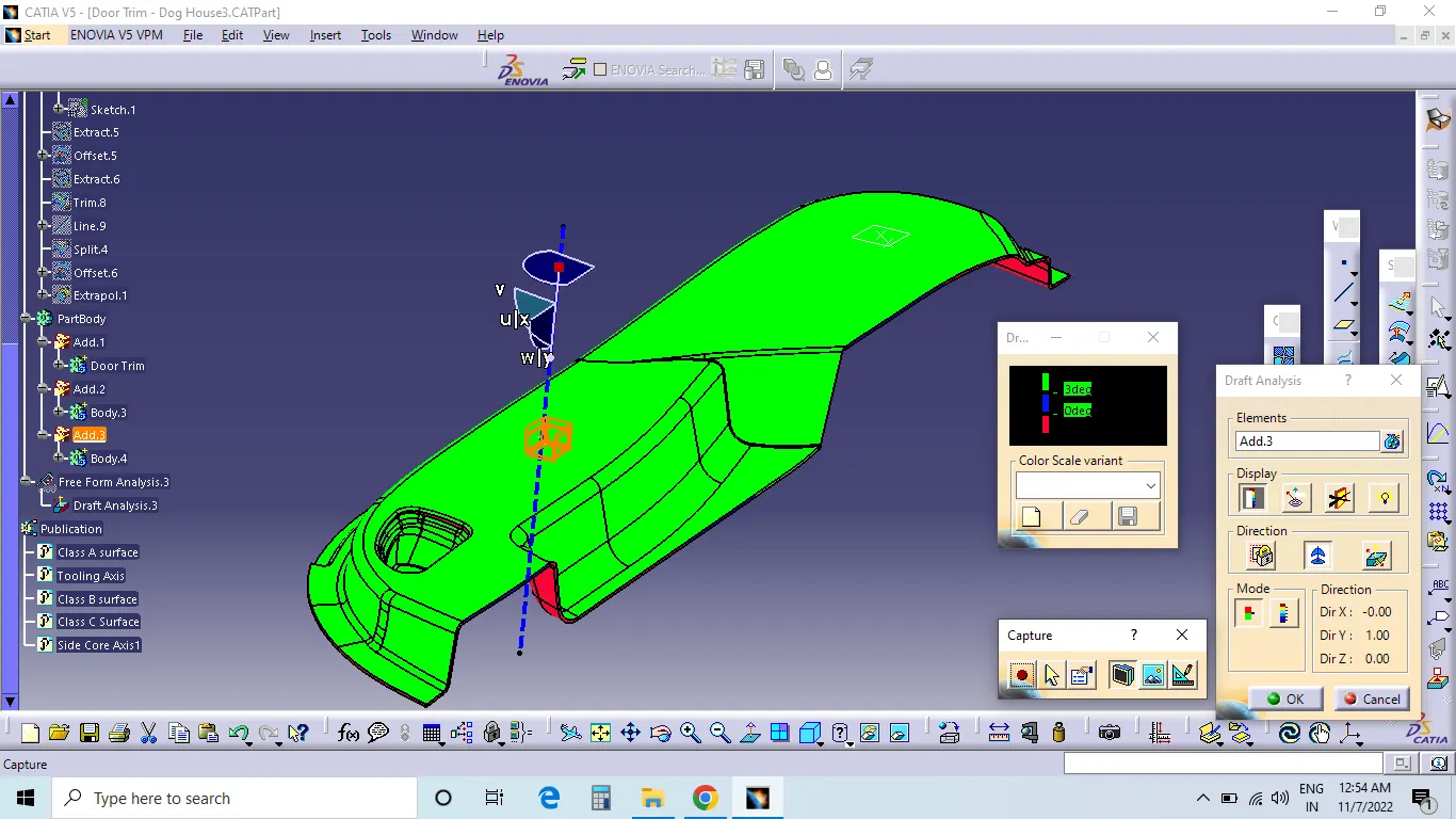
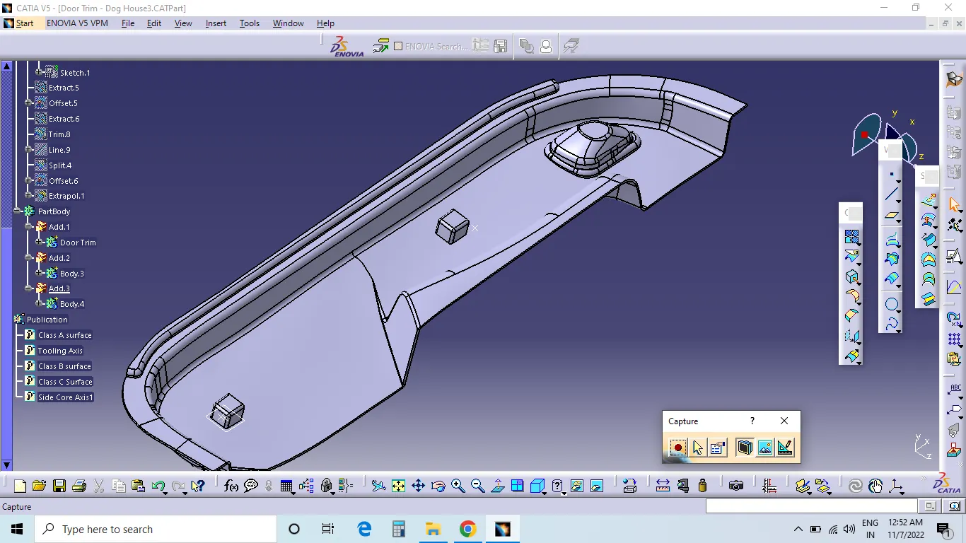
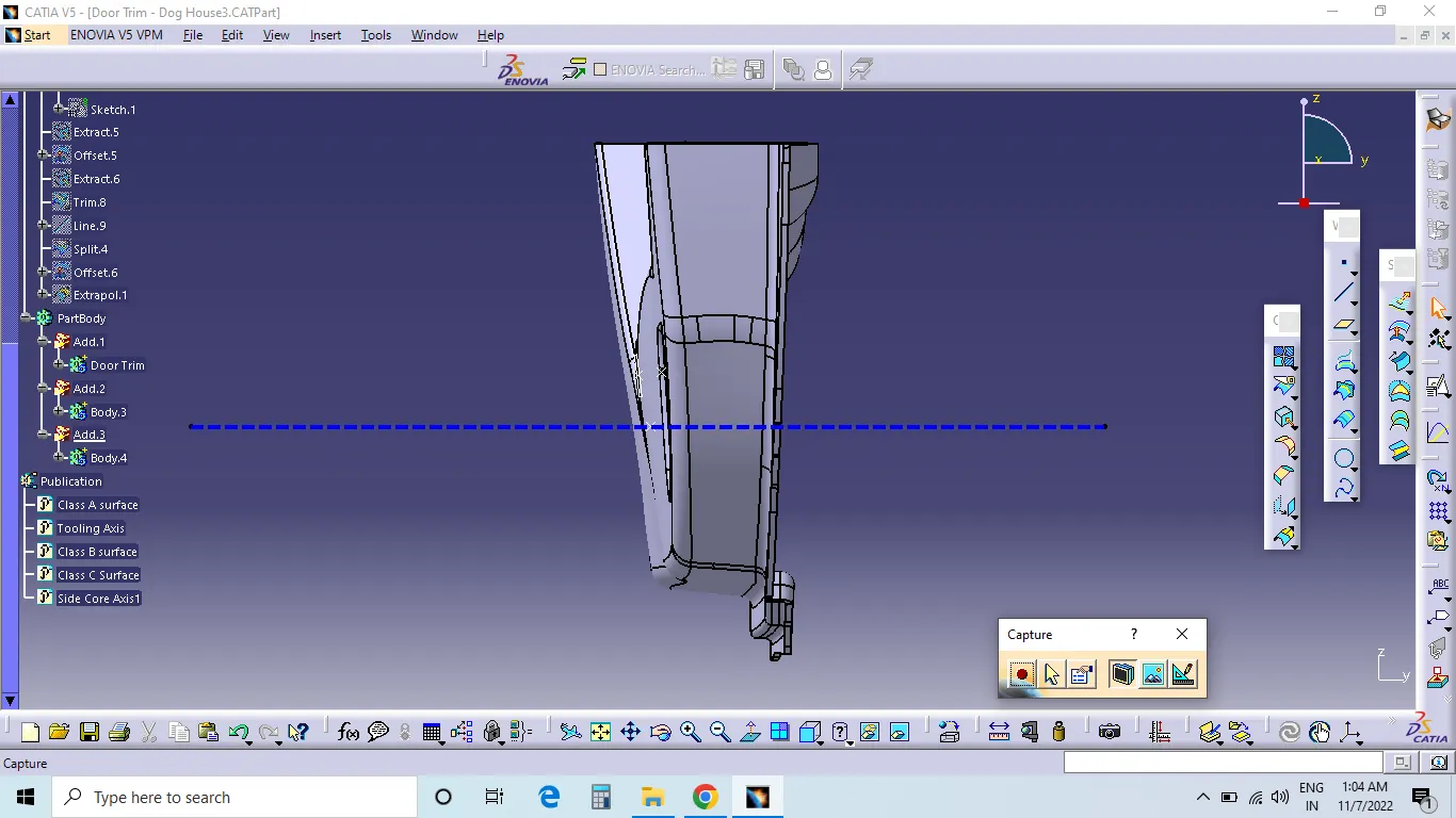
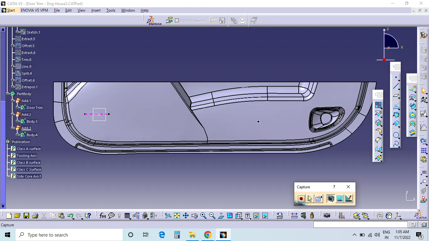
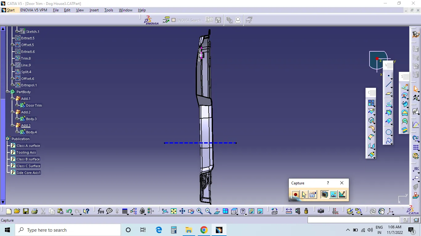
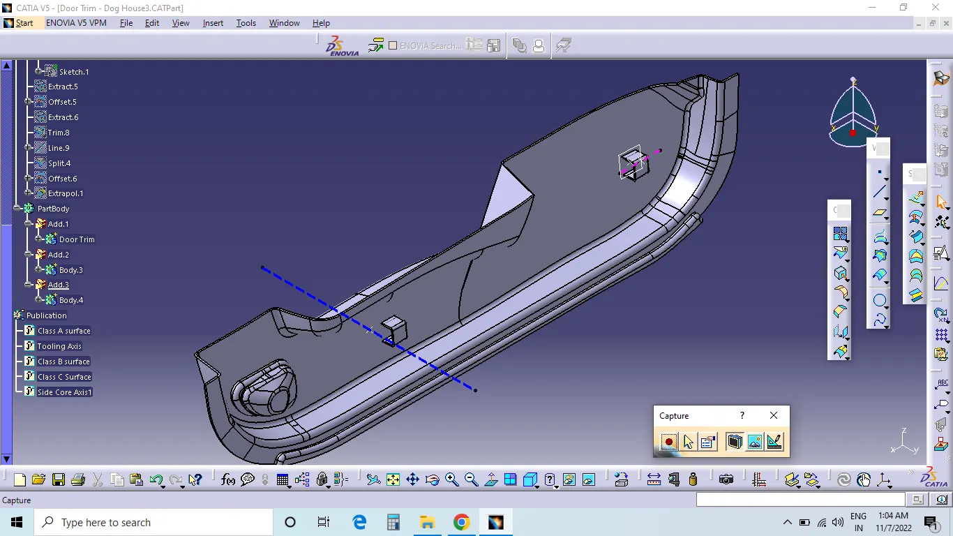
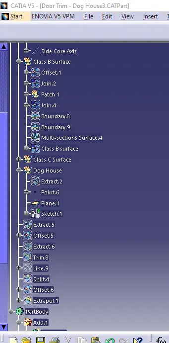
DOG HOUSE CREATION:-
The dog house is an engineering feature used in the plastic trim design. Dog houses are used as a supporting feature. Sometimes other engineering features like snaps; locators, etc. are mounded on them to increase their strength.
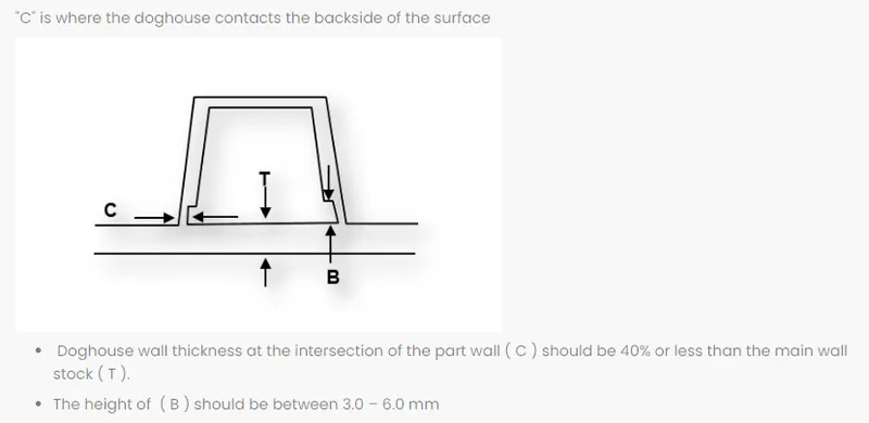
The doghouse is created by following the design rules.
The nominal wall thickness guide range is from 0.75 mm to 3 mm for reinforced materials and 0.5 mm to 5 mm for unreinforced materials.
Related Courses
WALL THICKNESS (W) = 0.70 (NOMINAL THICKNESS OF PLASTIC MATERIAL)
This process is usually done by Thicken surface command.
- Dog houses are designed to avoid SINK MARK created on the CLASS-A surface by screw bosses and to solve the length issues when giving screw bosses which need to be assembled to other components.
- It is also useful when perpendicular screw bosses are required on the part to the tooling direction.
Design Principle for Dog House Creation:-
CONCLUSION: I have successfully created CLASS B and C surfaces using the given CLASS A surface of the door trim created main and side core tooling axes. Performed draft analysis the the final component and the dog house.