Week 9 - Attachment Feature Creation - Challenge 2
DOOR TRIM FOR DOG HOUSE
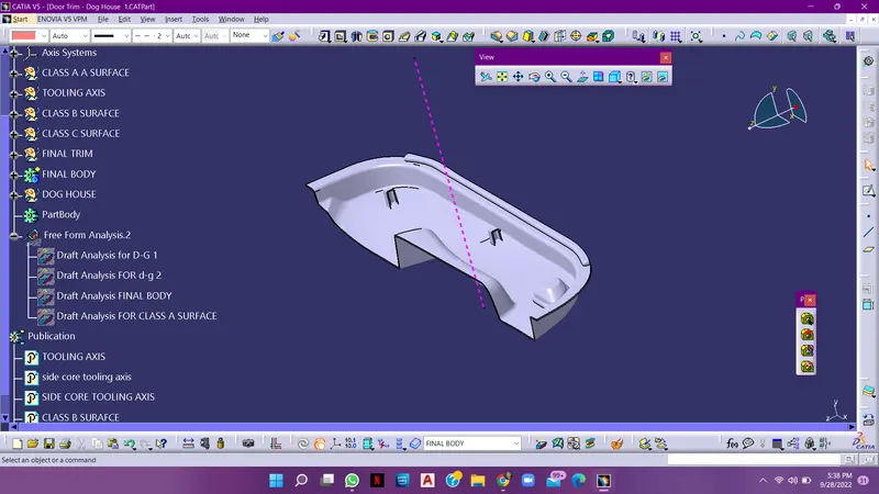
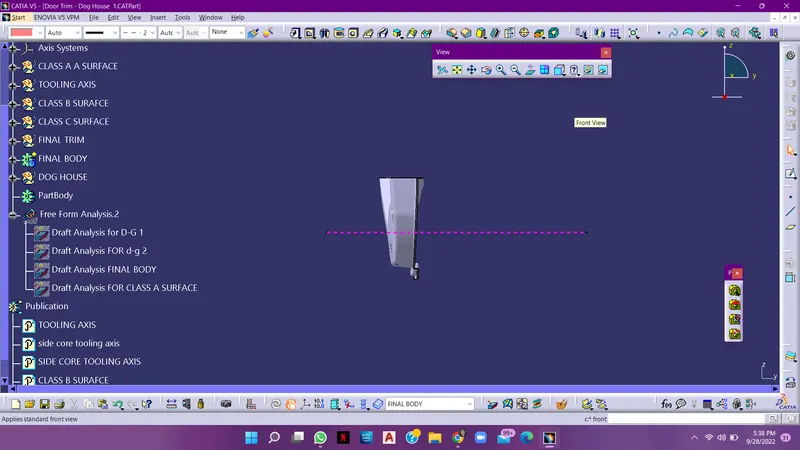
ISO METRIC VIEW FRONT VIEW
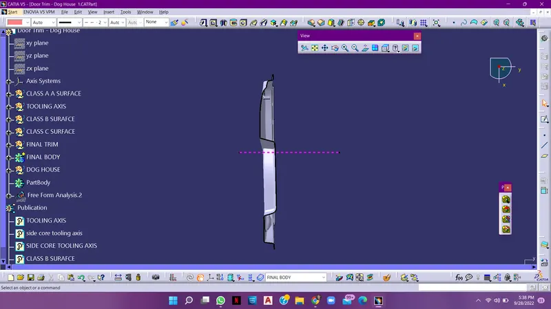
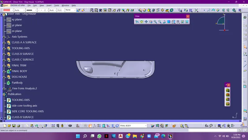
TOP VIEW SIDE VIEW
DRAFT ANALYSIS OF CLASS A SURAFCE
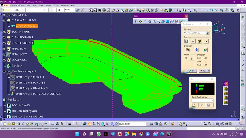
We can see that there is a negative draft at top and somewhat drafted between the 0-2.9 degrees in corner, so the same issue faced for the final draft also, so i have got the same negative draft for the final one.
DRAFT ANALYSIS OF A FINAL BODY
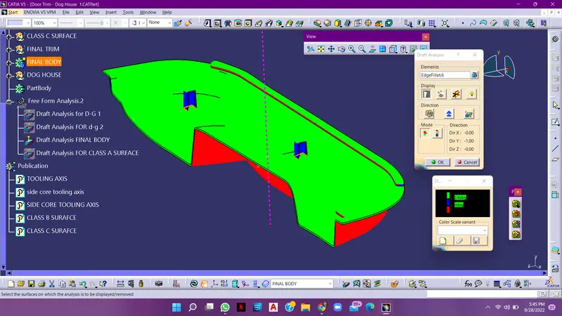
DRAFT ANALYSIS OF A DOG HOUSE - 1
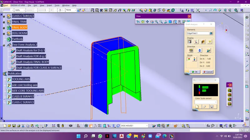
DRAFT ANALYSIS OF A DOG HOUSE 2
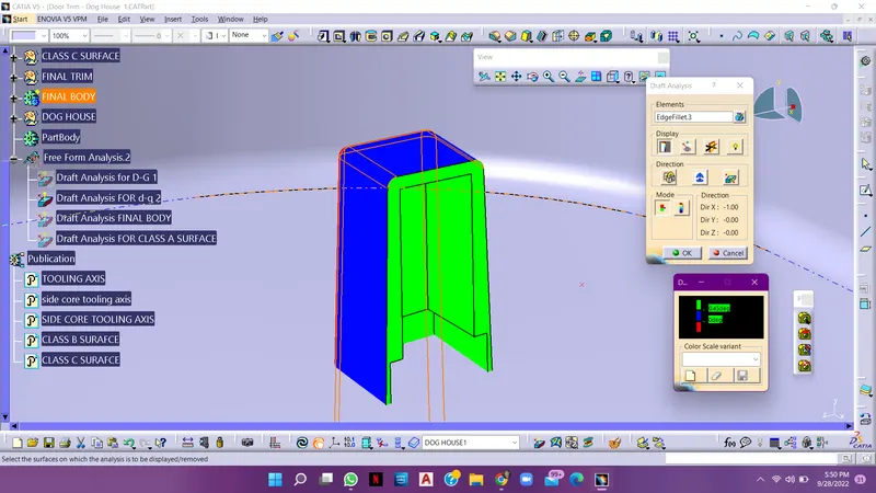
Report
Draft analysis -
Draft analysis is used to check, wheather the component is under the given draft angle or not ( draft angle shoulsd be 3 degress)
TOOLING AXIS
Tooling axis Creation Draft Analysis on CLass A Surface
The main objective is to create Draft Analysis by Providing the Tolling direction of a class a surface
-The draft analysis command enables you to identify wheather the component you drafted will be easily removed or not.
- After performing draft analysis we can able to recognize the material wih draft according to the colours allotted, according to the colours we can able to predecrt wheather the component is how much drafted.
- Tooling direction defines you, that in which direction that the component is being removed and the tooling direction was the main consideration for both plastic parts andd mould parts.
PUBLICATION SHOULD BE TAKEN FOR
-1 Tooling axis
-2 Class A suraface
-3 Class B surface
-4 Class C surface
-5 DOG HOUSES
-6 Final Body
TOOLING AXIS
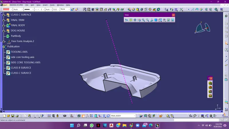
The above image shows the tooling axis, i have taken tooling axis with reffernce to the class a surface. i have selected a point and placed on the normal to the surafce and inserted a line and extended a line towards and downwards ( upto certain limit).
when the line is created, this will be your's tooling axis.
And after complete drafting it willl turns into the complete green colour ( that is we arranged thorugh choices of different colours). it indicates that the component is ready to manufacture
Creation of Class b surface-
I have offsetted the class a surface and tried to filled the gap my removing the fillet surafces with jion command( sub elements to remove ) and extrapolated the flat edges till thE other extraplotaed reaches the present one and trimmed it and this is how i filled the all the patches and then i extrapolated the outer boundary seepratly. And my class b surafce is done
Creation of Class C Suraface
I have created the class c surafce by sweep command tool ( taking the refference as a tooling axis ) and exteneded it by sufficient length( required) and i tried to filled th patches accured between the creation of class c surface. and i joind the class c surafce with the class a surafce. and my final class c surface has been created.