Week 8 - Challenge 6 - Core & Cavity Design
DREAFT ANALYSIS OF A SWITCH BEZEL FINAL BODY (FINAL BODY)
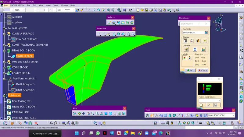
DRAFT ANALYSIS OF A CLASS A SURFACE
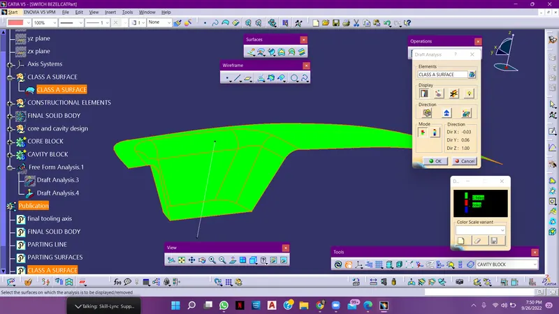
ISO METRIC VIEW FRONT VIEW
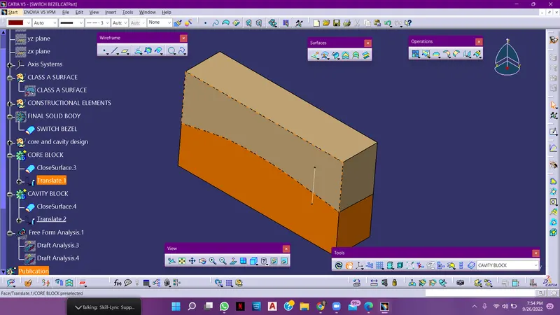
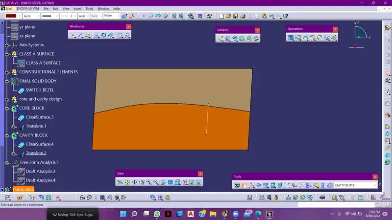
TOP VIEW SIDE VIEW
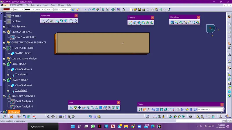
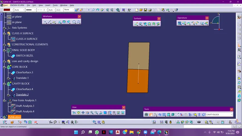
Tooling axis Creation Draft Analysis on CLass A Surface of switch bazel
The main objective is to create Draft Analysis by Providing the Tolling direction of a class a surface
-The draft analysis command enables you to identify wheather the component you drafted will be easily removed or not.
- After performing draft analysis we can able to recognize the material wih draft according to the colours allotted, according to the colours we can able to predecrt wheather the component is how much drafted.
- Tooling direction defines you, that in which direction that the component is being removed and the tooling direction was the main consideration for both plastic parts andd mould parts.
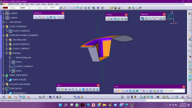
Tooling axis of the switch bezel
Report
Draft analysis - draft analysis is used to check, wheather the component is under the given draft angle or not ( draft angle shoulsd be 3 degress)
Tooling Axis - Tooling axis should be ensure properly in order to draft the component correctly. this tooling axis is taken by bisecting the lines derived by insection of the main component and also for creation of the class c, tooling axis plays the key role.