Week 9 - Attachment Feature Creation - Challenge 2
DRAFT ANALYSIS REPORT ON "DOOR TRIM WITH DOG_HOUSE".
STEP1.
STEP 1: using boundry command checked for any non intersecting surfaces, if found any should be done using appropriate commands and patch works, but in this case class A was all good.
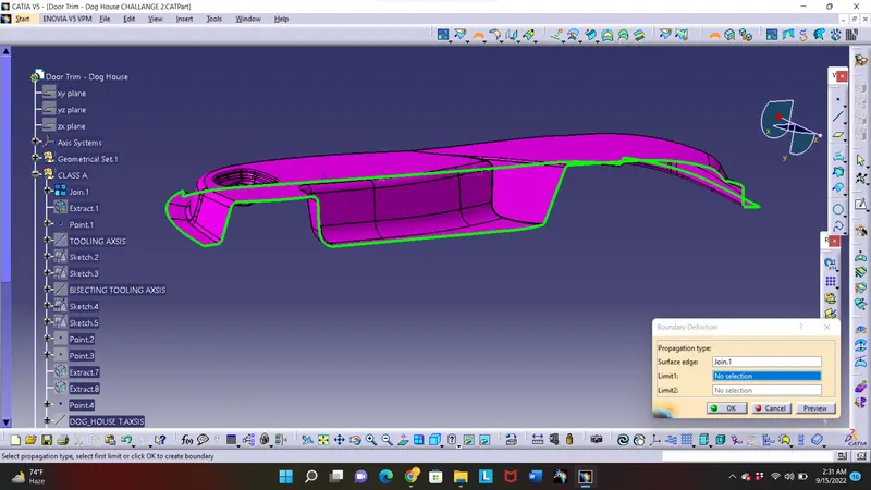
STEP 2:- using join command for creating single surface to work on, for reference for CLASS B, CLASS C.
STEP 2.
Draft analysis of class A,
STEP 1:
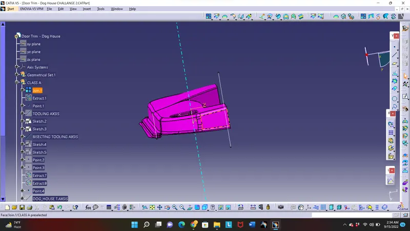
CREATION OF TOOLING AXSIS
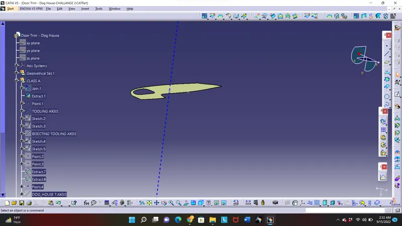
extract any surface of class A as shown in fig.
creat point on surface, and then take line normal to surface, actual tooling axsis should be normal to surface only because most of machinery available have only vreticle tooling axsis and horizontal axsis tooling direction.
CREATION OF BISECTING TOOLING AXSIS
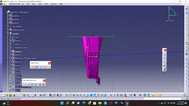
STEP 1:- draw two line sketch along the edges of componant on both side which might be inclined in some degree of angle for refrence for the bisecting tooling axsis ,
using 'bisecting' in line command, as shown below.
sketch 1.
sketch 2.
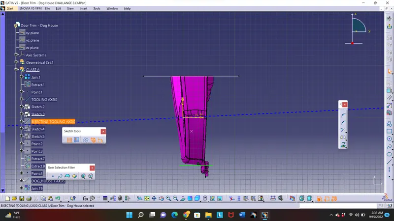
blue line is bisecting tooling axsis.
STEP 2:- insert draft analysis, place compass on tooling axsis and define the direction, and again place compass on tooling axsis and click on surface, following fig explains the process.
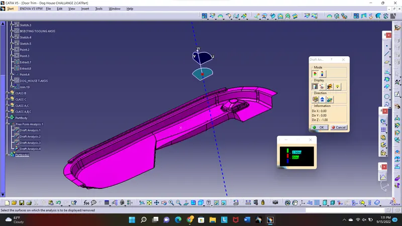
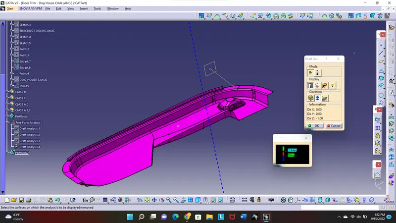
showing draft analysis.
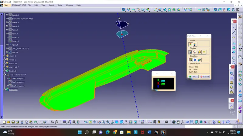
STEP 3.:- check for negative draft angle which might be present .
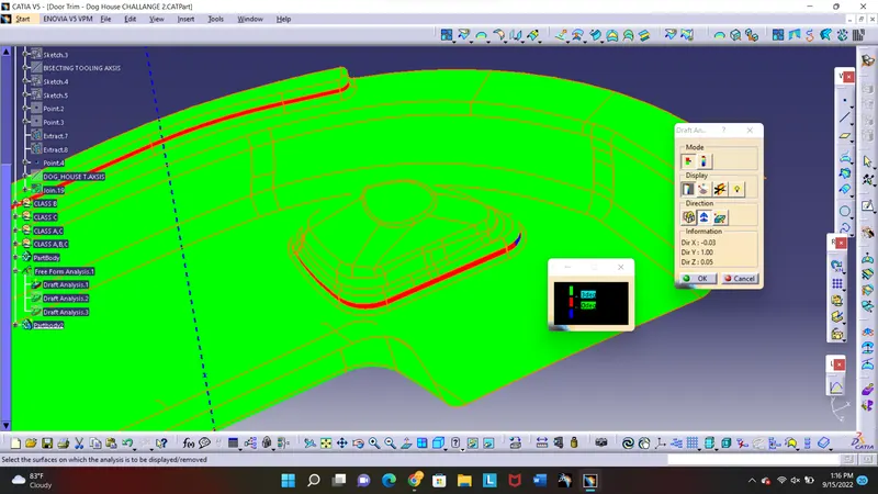
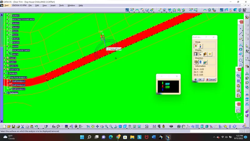
in draft analysis of given class A was not cleared by all surfaces, some of surface shows negative angle ,
this could not be cleared because the angle of surface is very low that its not techenically possible to manufacture core and cavity at this less angle which is 0.216degree.
this might also result in final componant as negative angle.
itration tried from 3degree to 0.5 degree for convinence.
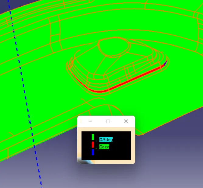
STEP 4:-
DRAFT ANALYSIS WITH BISECTING TOOLING AXSIS
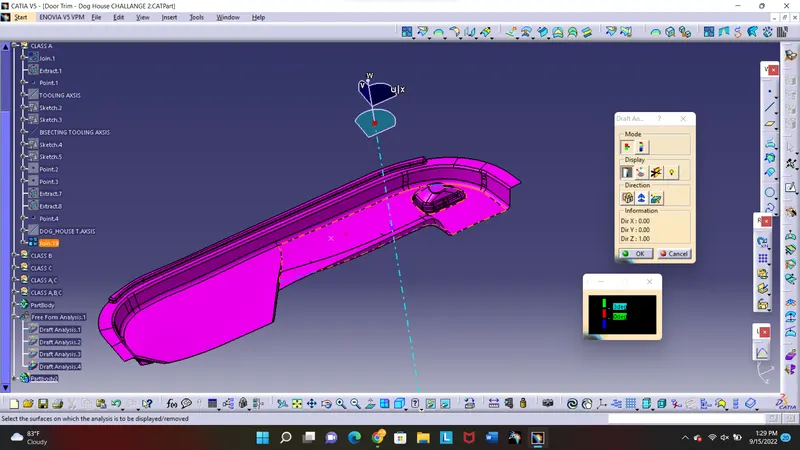
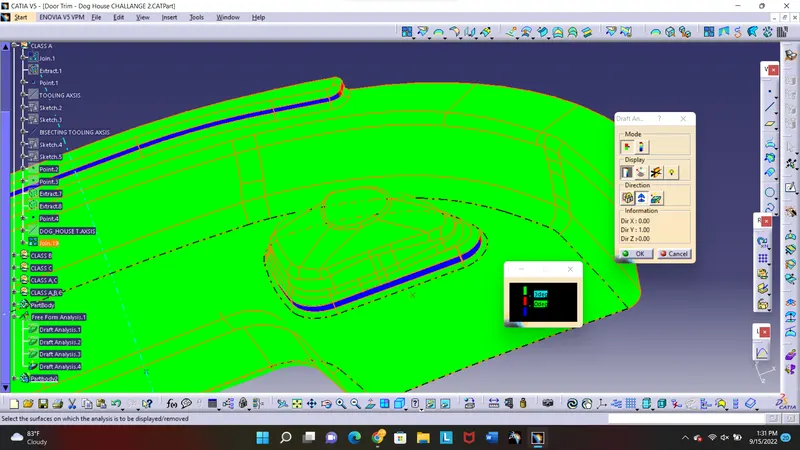
same results were shown with bisecting tooling axsis ,so there should be some correction in class a is what i think.
STEP 3.
CREATION OF CLASS B.
STEP 1:- extract surface from class A and offset it by 2.5mm beow the class A.
in some of parts offset of classA can give class B in one go but not all parts are designed in this way, so step by step is good method.
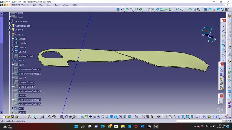
STEP 2:- making lower part ,
by untriming and then offseting method doesnot work here, so take multiple extract and join using join command and offset it , as shown.
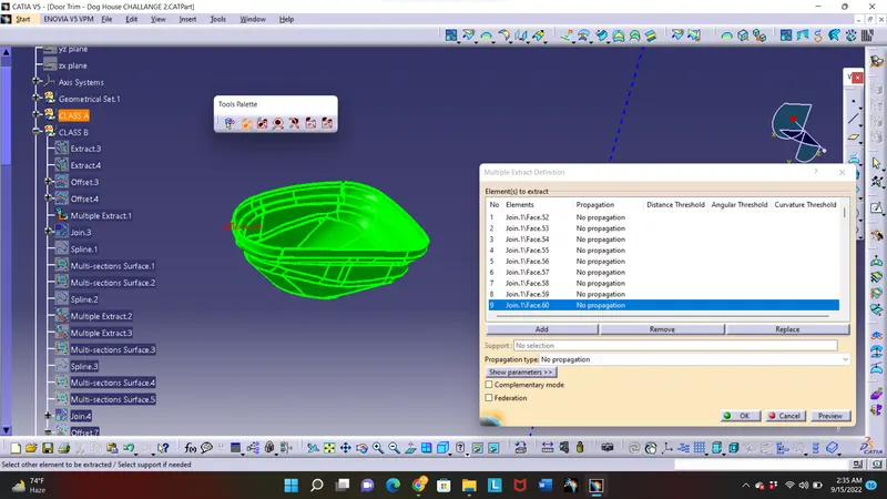
OFFSET IS SHOWN.
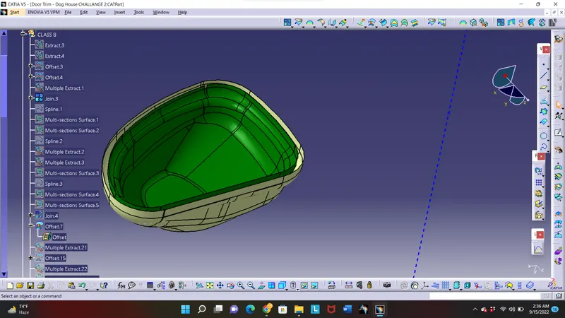
STEP 3:- by using all appropriate operations this is final class B .
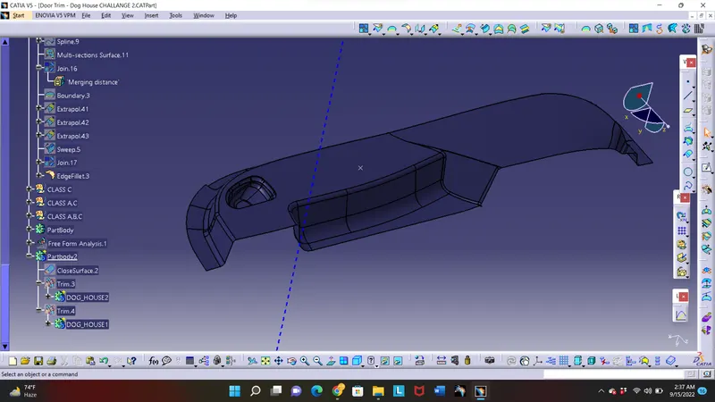
STEP 4.
CREATION OF CLASS C.
STEP 1:- extract boundry for sweo operation.
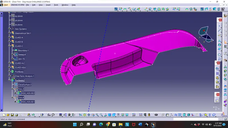
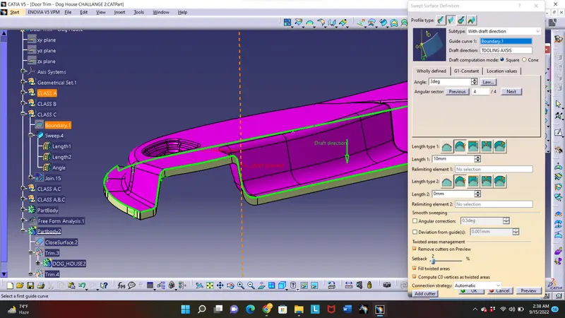
STEP 2:- by using swep operation swep class c in 3 degree outword direction as shown.
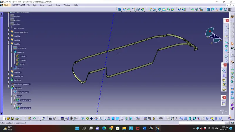
final class C.
STEP 5.
CREATING JOIN CLASS A,C
using join command or trim command join class A and class C.
CLASS A,C
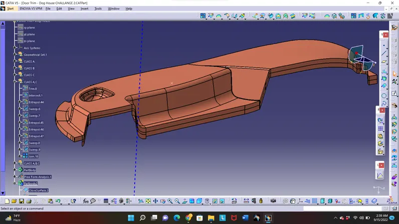
STEP 6.
CREATION OF CLASS A,C AND CLASS B.
STEP 1:- by using trim command trim class b with class a,c,
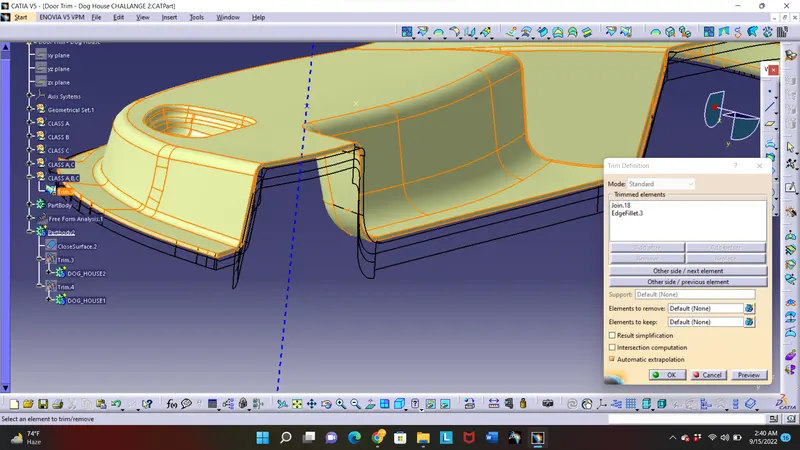
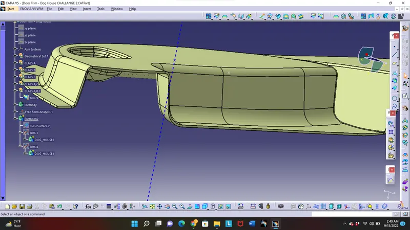
FINAL CLOSED COMPONANT .
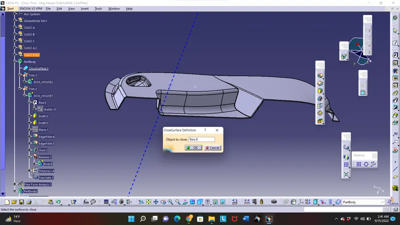
STEP 7.
CREATING SOLID COMPONANT USING CLOSED BODY METHOD.
STEP 8.
DRAFT ANALYSIS REPORT OF FINAL COMPONANT.
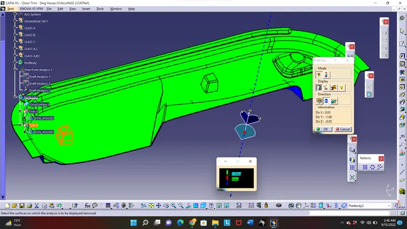
STEP 1:- insert draft analysis on solid body , place composs on tooling axsis and check results.
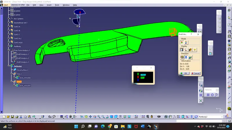
SOME EDGES SHOWS NEGATIVE DRAFT ANGLE AS SHOWN BELOW.
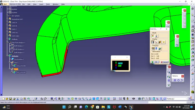
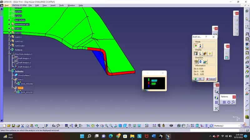
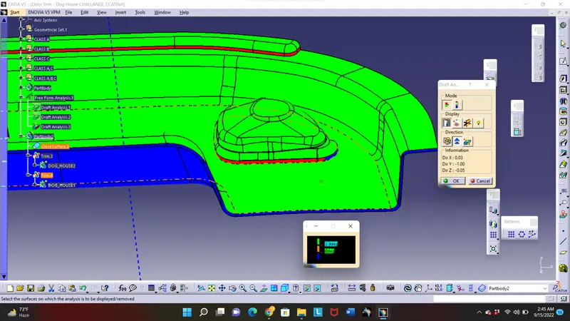
STEP 2:- by changing some angle of draft check clearence of draft.
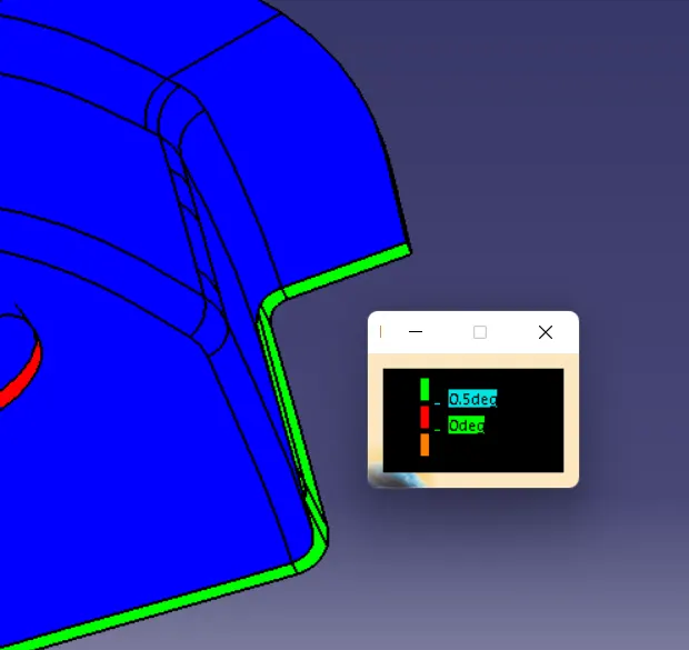
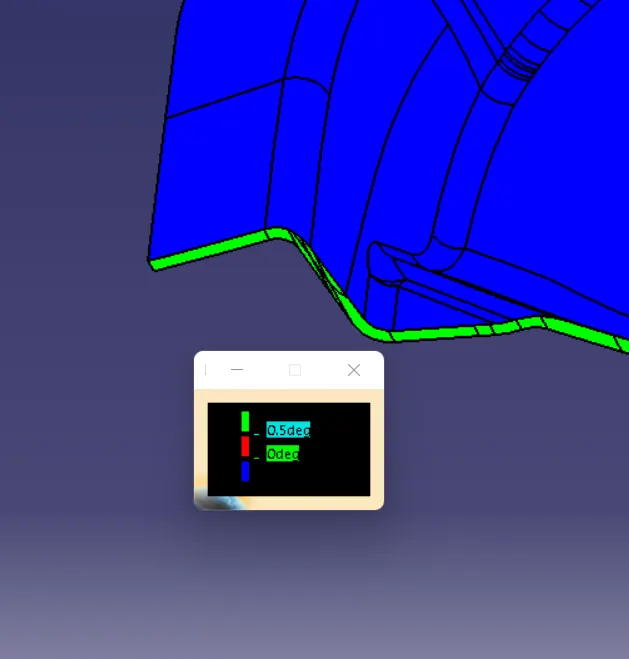
#note :- same results for bisecting tooling axsis.
step 9.
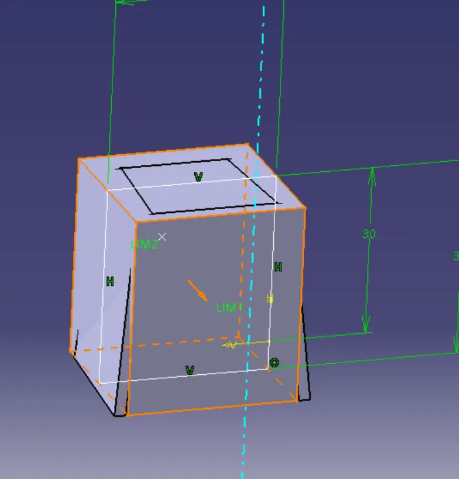
CREATING DIG HOUSE
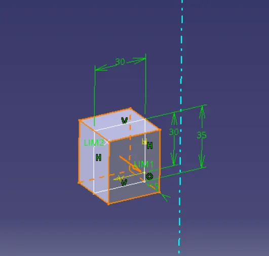
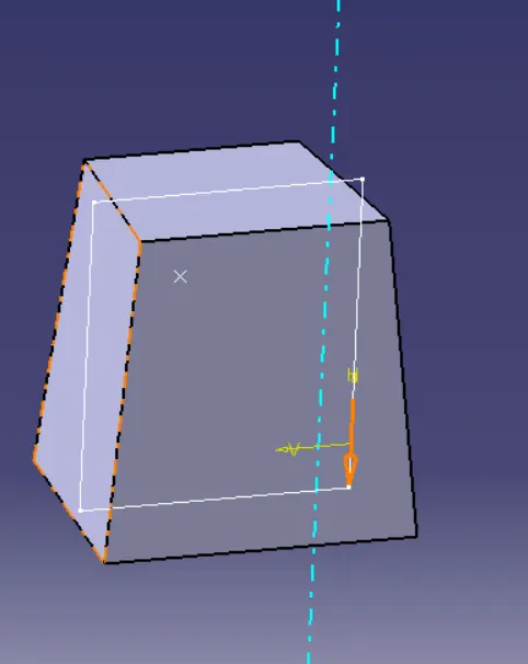
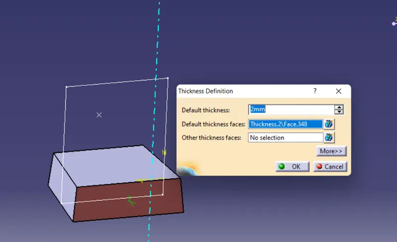
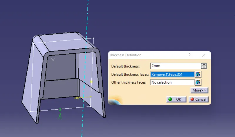
STEP 1:- take point on solid body surface and add axsis system to it and then draw sketch ,
draw sketch as per rules and pad it and provid expected draft and then union trim it with main body.
all process shown in fig below.
1) 2) 3)
4) 5)
5)
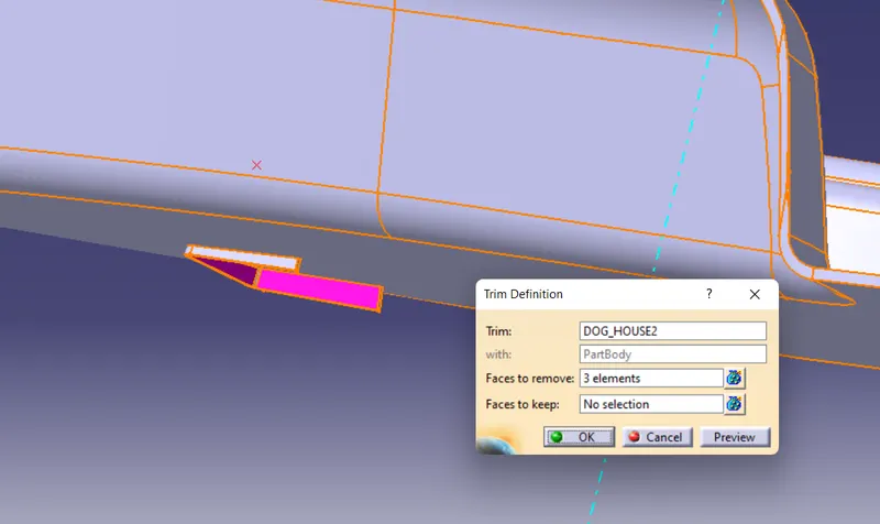
FINAL DOG_HOUSE
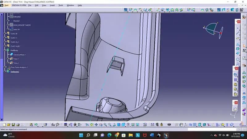
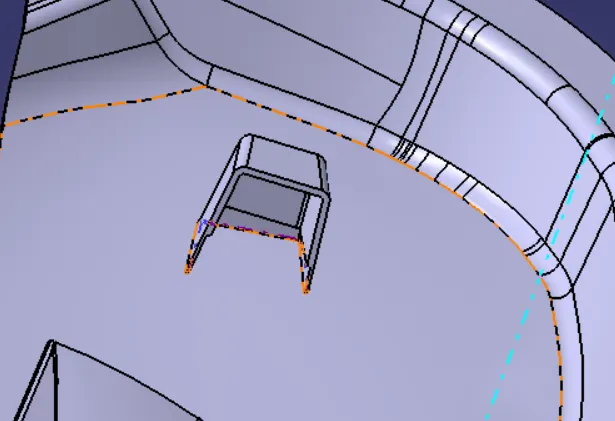
STEP 2:- translet dog_house using translate command by point to point .
STEP 10.
DRAFT ANALYSIS OF DOG_HOUSE
STEP 1:- Creat side way tooling axsis for dog_house ,
dog_house is ejected side ways so side way tooling is used for draft analysis.
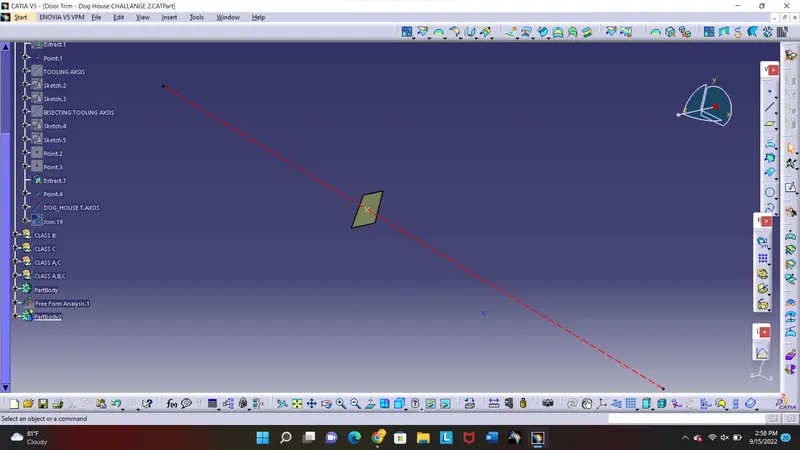
STEP 2:- check for clearance of draft .
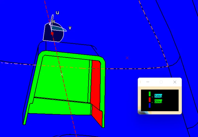
first dog_house at 5 degree angle.
second dog_house at 5 degree angle.
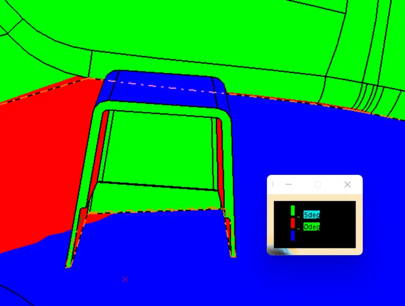
at 5 degree it does not cleared draft.
STEP 2:- try changing draft angle.
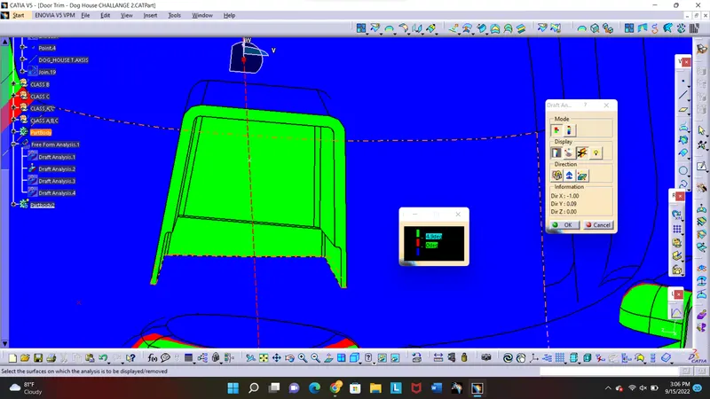
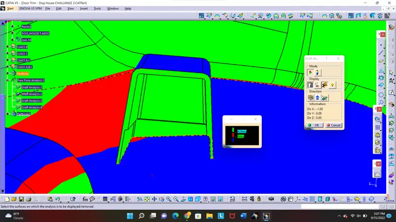
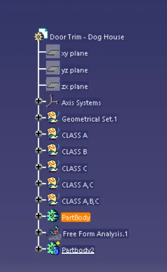
FINAL TREE STRUCTURE
#conclusion :-
draft angle was cleared at angle of 4.9 degree which is exceptable so dog_house can be ejected.